Imagine mastering the language of machinery with ease. This article decodes 45 essential press brake terminologies, offering clear definitions and practical insights. Whether you’re an operator, engineer, or enthusiast, you’ll gain a deeper understanding of these key terms, enhancing your proficiency in metalworking and press brake operations. Dive in to learn how these terms apply in real-world scenarios and improve your technical vocabulary, making complex concepts accessible and comprehensible.
Whether you’re a press brake manufacturer, end user, dealer, or service provider, the following 45 press brake terminologies will help you understand the professional expressions.
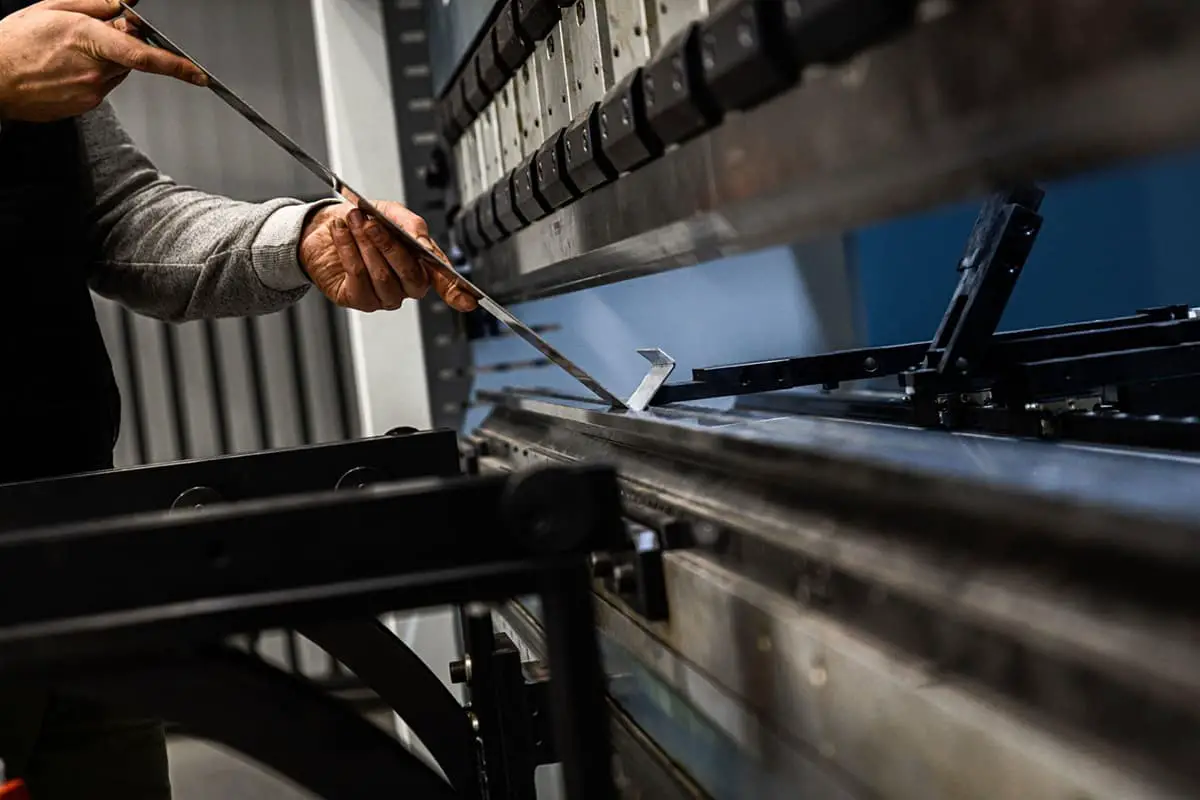
Back Gauge
An adjustable stop, automated on modern CNC machines, which acts as a stop for the workpiece centering the bend line over the V opening of the die.
Back Gauge Origin
A preset position for the back gauge, set from the center of the V opening. The back gauge origin is typically 4” from the center of the V. This origin will determine all positioning of the back gauge, so it’s crucial that it runs parallel to the die.
Bed Plate
The stabilizing and supporting foundation is a critical component of any brake press. This feature is often at ground level, although for some heavy-duty brakes and stamping machines, it will be located below ground and isolated from the floor to minimize the transfer of vibration from the machine to the floor.
Bottom Dead Center
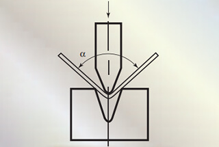
This is the position of the press brake when it is fully closed into the die. This position will be different for each die set.
Capacity / Tonnage
This is going to be the maximum force that the press brake can exert on the workpiece.
Clutch
The mechanism which engages the flywheel on a mechanical brake, transferring its energy through a gear set to the crankshaft, bringing tonnage down on the workpiece.
CNC
An abbreviation for Computer Numerical Control, this is a term applied to computer-controlled press brakes.
Crank Shaft
The component of a mechanical press brake which transfers the energy of the flywheel to the ram.
DayLight Through
A term used to describe the maximum open space a brake can open given a specific die set.
Down Acting Brake
A press brake where the upper beam moves the punch down into the die.
Flywheel
A large weighted wheel which is spun to store the energy necessary to close and re-open a mechanical press brake.
Foot Pedal
The part of a mechanical press brake which is used by the operator to engage the clutch.
Gibb Adjustment
Fine tuning motion control for the beam which will move.
High / Low-Speed Change
The point during the bending operation where the brake transitions from a high-speed motion to approach the workpiece to a low-speed motion to bend the workpiece is called the “slow bend point”. The bending is done at a slower rate to prevent dangerous whip-up of the workpiece.
Housing Brace
A structural component of the upper beam which holds the two driving cylinders of a press brake together.
Hydraulic Brake
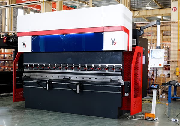
A press brake which is driven by the high-pressure transfer of fluid into a cylinder is called a hydraulic press brake. Hydraulic press brakes are known for their high accuracy and excellent control, and they are the most commonly used type of computer-controlled precision brakes.
Hydro-mechanical Brake
A press brake which uses a flywheel to push fluid to a hydraulic cylinder, offering even tonnage throughout the stroke, an advantage over typical mechanical brakes.
Length
The overall working length of the Brake Press beams from left to right.
Lower Beam
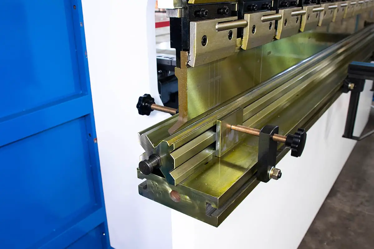
The lower portion of a press brake which holds the die or rail in position.
Mechanical Brake
A press brake which relies on a flywheel and clutch mechanism to mechanically transfer energy to cycle the ram is known as mechanical press brake. It is found on older machines and suffers from uneven tonnage application and poor vertical control.
Mechanical Stop
A physical stop which prevents older mechanical brakes from over traveling and improves repeatability.
Pinch Point
The moment the punch touches and begins to apply tonnage to the workpiece.
At this point, the back gauge may retract to allow the workpiece to form upwards freely.
Pit / No Pit Machine
Whether the machine requires a hole in the floor, and a subsequent base, to stabilize and secure the lower beam is referred to as a “Pit Machine”. Pit machines are typically much larger than “No Pit” machines.
Ram
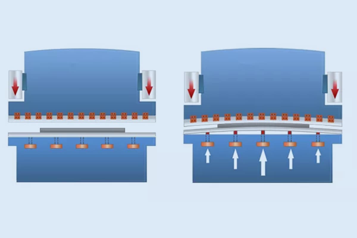
The upper and lower rams are the driving or resisting components of the press brake. They are typically machined from large, strong steel plates and can be complemented by internal hydraulic cylinders to resist deflection.
Repeatability
The accuracy with which the press brake is able to return to a specific position.
The maximum open size of the Brake Press, i.e. the distance between the top of the lower beam and the bottom of the upper beam when the brake is fully open and there is no tooling installed.
Swing Up Fingers
Special adaptation to the back gauge which allows the workpiece to move upwards without damaging the back gauge. These fingers are able to move freely with the part and out of the way.
Tandem
Two or more press brakes controlled by the same controller which are used to bend extremely large parts.
Throat
The depth of the press brake before the vertical supports limit flange length. Most press brakes are only constrained by the throat of a brake around the drive cylinders.
Top Dead Center
The compliment to bottom dead center, this is the position of the press brake when it is opened to its maximum height.
Tonnage Control
The ability of the machine to regulate its tonnage up to its maximum tonnage is referred to as tonnage control. This is greater with modern hydraulic brakes which can control their tonnage very accurately.
Up Acting Brake
A press brake where the lower beam moves the die upward into the punch.
Upper Beam
The upper portion of a press brake which holds the punch holder.
X-Axis
The front-to-back motion of the back gauge is called the X-Axis. It controls the flange length, with positive motion moving the back gauge towards the operator and resulting in a smaller flange.
R-Axis
The vertical motion of the back gauges.
Z-Axis
The left to right motion of the back gauge is called the Y-axis. This is used when bending with multiple setups down the press brake, allowing the gauges to move with the operator as they move the workpiece from one setup to the next.

