Adjusting the Light Path of the Laser Cutting Machine: A Step-by-Step Guide
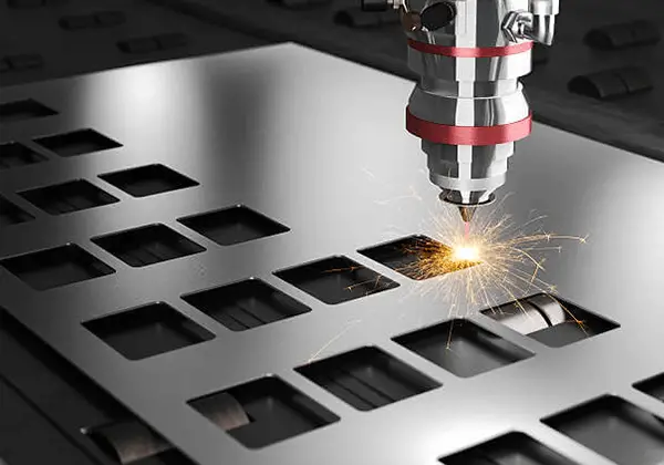
Why does your laser cutting machine sometimes fail to deliver precise cuts? The answer might lie in its optical path alignment. This guide walks you through the steps to adjust the light path, ensuring your laser maintains optimal performance. By understanding and adjusting the positions of the laser tube, reflectors, and focusing lenses, you’ll achieve cleaner, more accurate cuts. Dive into the specifics and learn how to keep your machine in peak condition.
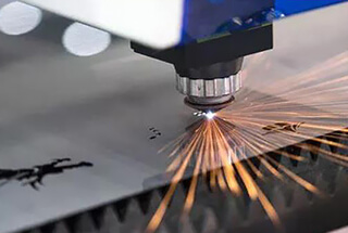
Laser cutting involves focusing a laser beam through a focusing mirror to concentrate it into a small point of light, which is then projected onto a metal surface.
The focus point attains a high power density.
At this point, the irradiated section of the material heats up rapidly and reaches the temperature of vaporization, resulting in the formation of a hole.
Through the relative linear motion of the beam and the material, the hole will continue to elongate and become a very narrow slit, ultimately achieving the goal of cutting materials.
If the laser cutting machine operates for extended periods, its optical path may deviate, leading to an adverse impact on the quality of the cuts.
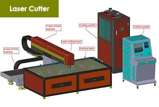
The optimal performance of a laser cutting machine relies on the perfect coordination among its key components: the laser tube, the reflector frame (A, B, C), the focusing lens, and their corresponding adjustment devices. These elements work together to produce the highest quality output and are therefore considered the core components of the laser cutting process.
Therefore, it is necessary to check the optical path and adjust it regularly.
Components and structures
Reflector frame A
1. Optical target placement rack
2. Reflector
3. Tension spring locking screw
4. Adjusting screw
5. Adjusting nut
6. Locking screw a
7. Locking screw b
8. Adjusting screw M1
9. Mirror locking piece
10. Adjusting screw M
11. Adjusting screw M2
12. Tension spring
13. Mounting plate of reflector
14. Support plate
15. Base
Reflector frame B (its mounting base plate is different from that of mirror frame A and the rest are the same).
1. Install the bottom plate (movable left and right)
2. Locking screw
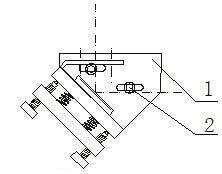
Reflector frame C
1. Mirror adjusting plate
2. Reflector
3. Locking screw
4. Adjusting screw M1
5. Mirror adjusting plate
6. Mirror pressing plate
7. Adjusting screw M
8. Locking screw
9. Adjusting screw M2
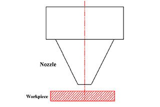
Focusing lenses
1. Focusing mirror inner cylinder
2. Air intake pipe
3. Limit screw ring
4. Air nozzle transition sleeve
5. Air nozzle
6. Lens tube
7. Limit screw
8. Adjusting sleeve
After knowing the name of each component, let’s teach you how to adjust the light path of the laser cutting machine:
Four light path adjustment
(1) Adjustment of the first light path
Place the masking paper on the dimming target hole of reflector A and manually adjust the light (note that the power should not be too high at this stage). Fine-tune the base of reflector A and the laser tube bracket until the light accurately hits the center of the target hole. It is important to ensure that the light is not blocked during this process.
(2) Adjustment of the second light path
Move reflector B to a remote location and use a piece of cardboard to guide the light from near to far into the cross-light target. This is because if the remote light is in the target, the near end must also be in the target.
Then, adjust the near end and remote light spot so that they are the same. This means that the deflection of the near end should match the deflection of the remote end, resulting in the cross being in the same position in both the near end and remote light spot. This will indicate whether the light path is parallel to the Y-axis guide rail.
(3) Adjustment of the third light path
(Note: The cross divides the light spot into left and right sections.) Move reflector C to the remote position to guide the light into the target. Shoot the target at the inlet and remote once and adjust the position of the contrast cross to match the position of the cross in the near-end light spot. This indicates that the beam is parallel to the X-axis.
If the optical path is inward or outward, loosen or tighten M1, M2, and M3 on mirror frame B until the light splits into left and right sections.
(4) Adjustment of the fourth light path
Place a piece of masking paper over the light outlet and press it down gently. The hole in the light outlet should leave a circular mark on the adhesive tape. Remove the masking paper and turn on the light. Next, carefully observe the position of the small hole and make adjustments to M1, M2, and M3 on the mirror frame C as necessary until the light spot appears round and straight. Finally, remove the adhesive tape from the light outlet.
As the founder of MachineMFG, I have dedicated over a decade of my career to the metalworking industry. My extensive experience has allowed me to become an expert in the fields of sheet metal fabrication, machining, mechanical engineering, and machine tools for metals. I am constantly thinking, reading, and writing about these subjects, constantly striving to stay at the forefront of my field. Let my knowledge and expertise be an asset to your business.
Ever wondered how lasers can slice through steel with pinpoint precision? In this article, we unravel the secrets behind laser cutting. From laser modes to nozzle adjustments, discover how each…
Ever wondered how precision in laser cutting is achieved? This article explores the crucial factors influencing laser cutting quality, such as nozzle condition, focus position, and auxiliary gas pressure. By…
What if adjusting the focus of your laser cutter could mean the difference between a clean cut and a failed project? In laser cutting, the focal point's position is crucial…
Ever wondered how to ensure top-notch quality in laser cutting? This article outlines nine essential standards for evaluating the precision and effectiveness of laser cuts. You'll learn to assess factors…
Have you ever wondered how a powerful laser beam can cut through metal like a hot knife through butter? In this fascinating blog post, we'll explore the inner workings of…
Ever wondered how lasers can cut through metal like a hot knife through butter? This article dives into the fascinating world of laser cutting, focusing on the crucial role of…
Ever wondered how laser cutters can slice through metal like butter? This article explores the fascinating world of laser cutter wattage and its impact on cutting speed and material compatibility.…
Curious about the capabilities of laser cutting? In this comprehensive guide, we'll dive into the world of laser cutting speeds and thicknesses for various metals. Our expert mechanical engineer will…
Have you ever wondered what makes a laser cutting machine tick? In this blog post, we'll dive deep into the inner workings of these high-precision machines that have revolutionized the…