Our air bending force chart, based on the experience data of customers from various industries worldwide, provides an authoritative guide to help you easily determine the minimum bending pressure, minimum flange length, and bending radius corresponding to different V openings when bending mild steel and stainless steel.
With this chart, you can save time and increase efficiency in your bending process.
Additionally, our press brake tonnage calculator can assist you in calculating the required bending force for your specific sheet metal product.
We understand the importance of selecting the most appropriate V-opening, and our chart shows the optimum relationship between metal thickness and V-opening width.
Air Bending Principles
Tonnage Requirements
Air bending is the preferred method of forming sheet material with a punch and die combination. Lower forming tonnage allows press brakes of lower capacity to manufacture the formed parts.
Figure below details the relationship between material thickness and die opening for a specified material tensile strength of 60,000 PSI. Note that as the tensile strength of most mild steels in North America exceed 60,000 PSI, higher tonnage values may be required.
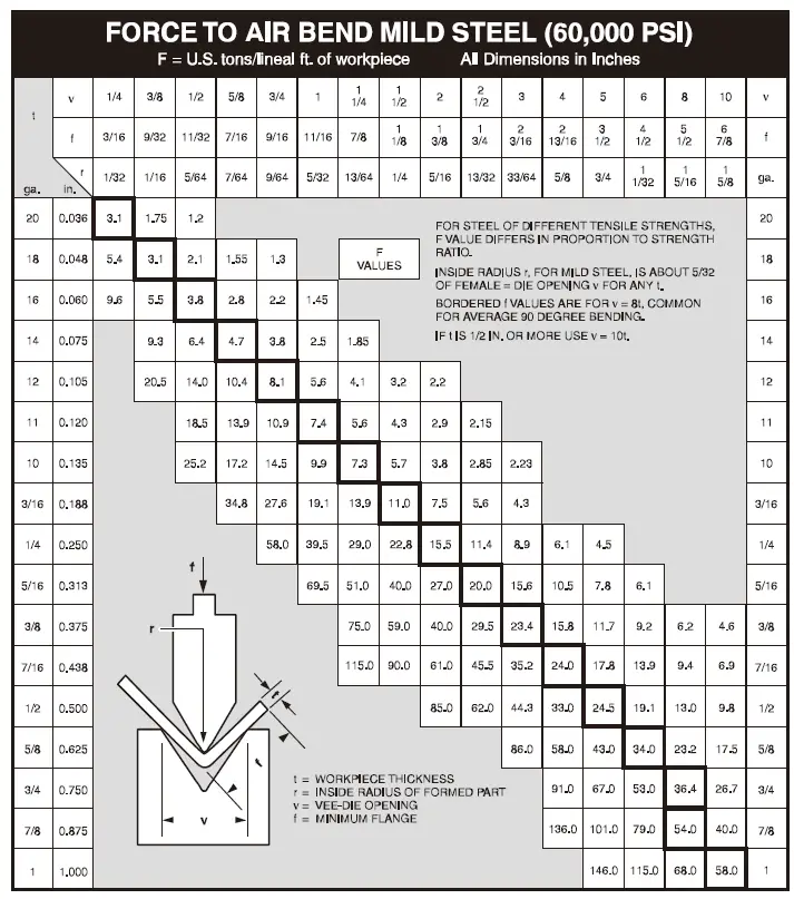
Note:
The above chart illustrates the appropriate tonnage values to air bend mild steel with 60,000 PSI tensile properties. It must be noted that most North American steel mills are producing harder metals with typical mechanical properties of 44,000 PSI yield and up to 80,000 PSI tensile strengths. The tonnage values required to form these metals are substantially higher and must be taken into consideration in the selection of a press brake.
Die to Material Thickness Ratios
Standard industry practice for sizing the die opening is: eight times material thickness when less than 1/2”, ten times material thickness when 1/2” and greater.
For material in a heat treated condition, some material data sheets may specify larger die openings to prevent the formed shape from cracking.
For gauge sheet material and light plate, the punch radius is typically equal to the material thickness. For heavy plate, the punch radius is normally one and a half to three times the material thickness, depending on the properties of the plate being formed.
Air Bending Force Chart Background
The air bending force chart records the standard lower die V width and the required bending force corresponding to the bending of different sheet metals and has become a general industry specification.
However, there was no such specification at first.
Each press brake manufacturer decided to use the V-width based on their own experience.
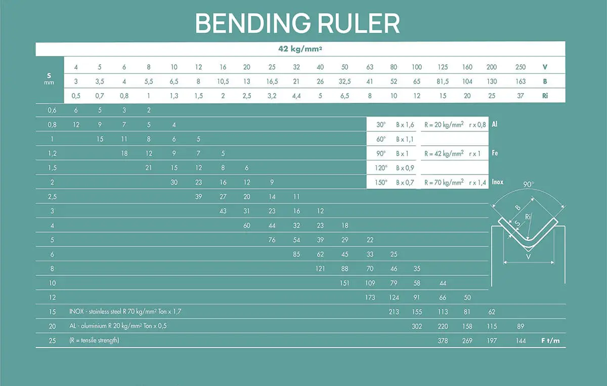
At that time, Amada collected and summarized the experience data of customers from various industries worldwide and finally made the following authoritative bending force chart for the bending process.
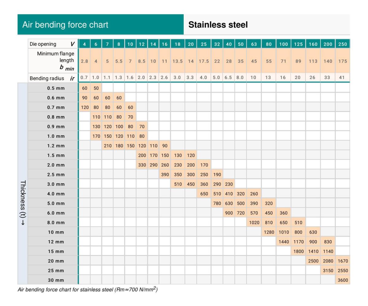
Through this bending force chart, you can easily determine the minimum bending pressure, minimum flange length, and bending radius corresponding to different V openings when bending mild steel and stainless steel.

- t – Material thickness
- F – Tonnage per 1 meter
- ir – inside radius
- b – minimum flange length
- V – V-width
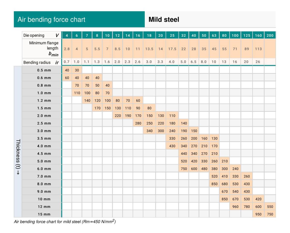
Air Bending Force Chart – Mild Steel
Air Bending Force Chart – Stainless Steel
To facilitate your reading and printing, you can download the PDF file of the air bending force chart.
You can also use our press brake tonnage calculator to calculate the required bending force for your sheet metal products.
FAQs About Air Bending Force Chart
How to Read the Air Bending Force Chart?
You can get the following information from the air bending force chart above if the data of the metal thickness and bending inner raidus are known:
- Required bending force to bend metal sheet of 1 meter length
- V-opening width
- Minimum flange length
How to Select the Most Appropriate V-Opening?
The V-opening refers to the distance across the lower die mouth, and the appropriate V-opening of the die should be selected according to the sheet metal thickness. The air bending chart above shows the optimum relationship between the metal thickness and V-opening width.
However, other factors will affect the selection of the V-width, including flange lengths, inner bending radius, press brake tonnage, and the capacity of the tooling.
What Is the Best Relationship Between Metal Thickness and v Opening?
| Material Thickness (t)mm | 0.5-2.5 | 3.0-8.0 | 9.0-10.0 | ≥12.0 |
| V-Width | 6xt | 8xt | 10xt | 12xt |