Why do aircraft use rivets instead of welding? The answer lies in the unique challenges of aerospace engineering. Riveting offers greater stability and reliability, essential for the thin, lightweight materials used in airplanes. Unlike welds, which can suffer from heat damage and fatigue over time, rivets provide consistent quality and ease of maintenance. This article delves into the reasons behind the industry’s preference for rivets, exploring the benefits they offer in terms of production, performance, and safety.

Upon close inspection of an airplane, we can observe numerous rivets on its skin. This riveting process is also commonly seen in the construction of large bridges.
It’s said that a C919 airplane requires millions of rivets, while the A380 passenger jet uses over five million.
So, why don’t they simply weld the airplane instead of choosing this seemingly cumbersome riveting process?

In the aerospace industry, there’s a motto: “Striving to shed every single gram.” To lighten the aircraft, manufacturers use the lightest possible materials, tailored to specific applications.
The skin of an aircraft is generally made very thin in order to reduce weight. The challenge of welding such thin skins together is enormous.
Furthermore, some aircraft bodies are made of aluminum, which has relatively poor heat resistance. The welding process generates a large amount of heat, which is clearly unsuitable for aircraft with aluminum bodies.
The most advanced commercial aircraft internationally make extensive use of composite materials. These materials can also be damaged by welding. The connection between different materials must be secured in a physical manner.
During my first airplane ride, I was seated near the wing window. When the plane encountered turbulence, the wing noticeably trembled, causing a surge of anxiety within me.
I believe many of you have witnessed such scenarios where, if the turbulence is severe, the airplane’s wing would swing dramatically.
Throughout this continuous swinging process, the wing’s skin would either be stretched or compressed. If a welding process was used, the strength at the welding points would significantly decline under these recurring stress changes.
Over time, these welded areas might develop tiny cracks. If not discovered in time, they pose a substantial safety hazard.
Commercial airplanes usually serve for over a decade, and weld seams are prone to metal fatigue problems, resulting in suboptimal connection. Conversely, riveting can reduce vibration transmission between connected parts, thereby lowering the risk of vibrational cracking. In terms of recurring stress changes, riveting provides superior and more reliable firmness.
Welding quality largely depends on the skill of the operator, with substantial randomness whether it’s too thin or too thick. It’s challenging to establish uniform standards.
In contrast, the rivets used in the riveting process have minimal parameter errors, making quality control and standardized production easy.
Everyone knows that during aircraft manufacturing, the demand for standardization is high.
The most critical aspect in the aviation industry is quality consistency. An aircraft has millions of rivets, and the first rivet produced must be identical to the tens of millions that follow.
The strength requirement for rivets on an aircraft is as high as 1100 megapascals, equivalent to the weight of ten sedans on one square centimeter. The precision of rivet processing reaches micron-level control.
This concept is similar to that of large aircraft themselves. Manufacturing a cutting-edge large aircraft is not too difficult for a major country, but producing thousands of identical products is a monumental challenge.

Some may wonder: wouldn’t these conspicuous rivets increase the aerodynamic drag of the aircraft? In fact, the rivets used in aviation manufacturing are primarily of the protruding head and countersunk types.
Inside the aircraft, where there is no need for aerodynamic shaping, the lower-cost, easier-to-process protruding head rivets are predominantly utilized.
Countersunk rivets, on the other hand, are mainly used on the aircraft’s exterior parts that need to be smooth. They can effectively reduce the aircraft’s drag. The manufacturing process requires strict tolerances for the rivet caps and nearby structures. When you touch the surface of the aircraft, you can hardly feel the presence of the rivets.
This application has yielded significant results. According to data from World War II, the use of countersunk rivets can reduce the aircraft’s drag by approximately 3%.
Typically, we use a frozen rivet for replacement. This rivet is rapidly cooled after heat treatment and must be riveted within fifteen minutes of use.
Such a frozen rivet’s strength increases under normal temperature conditions, thereby enhancing the stability of the riveted structure.
A single loose rivet could potentially trigger an aircraft malfunction alert, necessitating round-the-clock overtime for maintenance staff to locate the problematic rivet.
In 2016, to troubleshoot an issue with an A320 aircraft, maintenance personnel labored relentlessly for three days and nights. After systematically investigating all possible faults, they finally identified a loose pin among hundreds of data pins, each less than 1 millimeter in diameter.
While the task of identifying and fixing rivet faults can be demanding, it’s not a cause for concern. Aviation screws are self-locking, making the likelihood of loosening minute.
Due to various constraints, most of the aircraft we see today are assembled with rivets.
Individual pieces of aircraft skin are interconnected using rivets, effectively forming an airborne armor. This allows the aircraft’s flaps to move flexibly.
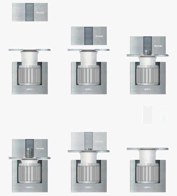
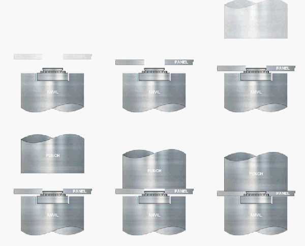
Press riveting is a method of fastening that applies external pressure to alter the plasticity of the material in the engineering process. This technique allows the insertion of rivet screws and nuts into specialized prefabricated slots in the structure, thereby achieving a reliable connection between components.
Common low-carbon steel, aluminum alloy sheets, and copper sheets are typically used for press-fit rivet nut studs. For materials of excessive hardness, such as stainless steel and high-carbon steel plates, specially made, highly hard rivet nut studs are used. Consequently, stainless steel is seldom utilized in general press rivet studs and press rivet nut sheet metal parts. The same applies to press rivet screws and nuts, where stainless steel is infrequently used.
Through the analysis of press riveting processes, along with introductions to common press riveting components and their techniques, and in conjunction with quality control methods of press riveting operations, a comprehensive discussion on press riveting processes has been undertaken.
1. The hole size for rivet placement must be made in accordance with the standard hole size chart.
2. Except in special cases (such as when interference occurs with riveting after all machining and surface treatment has been completed), surface treatment of the product must be completed before the riveting process.
3. When selecting the color of the riveted parts, if color zinc plating is selected on the product parts, the riveted parts should match. For blue zinc, white zinc, nickel, and oxide plating on the product parts, nickel-plated riveted parts are typically used. For special product parts that need to be riveted before surface treatment and require brazing reinforcement, nickel-plated riveted parts are also chosen, as the chemical properties of the plating layer impact the quality of the welding.
(I) Rivet Nuts and Their Processing Requirements
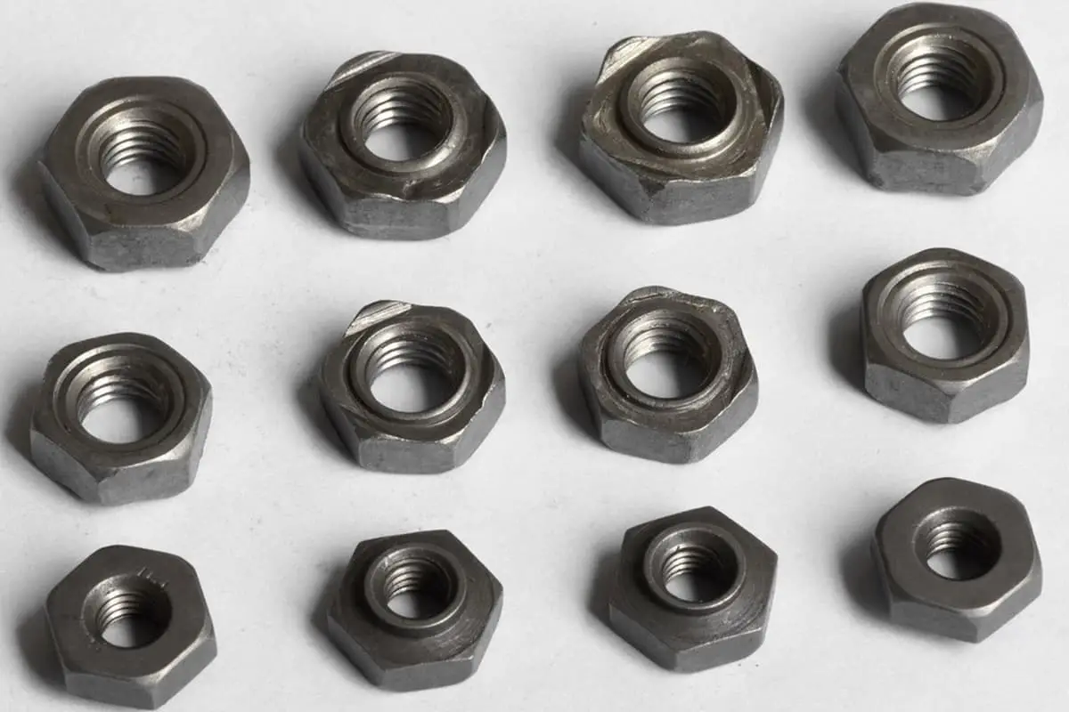
When the thickness (t) of the flower tooth rivet nut’s aluminum plate is less than or equal to 1.0mm, the processing code -0 is used. For riveting with stainless steel materials, because stainless steel is hard and tends to make the rivet nut fall off after riveting, spot welding is usually employed around the nut to strengthen it.
During the riveting process, the die must be in place in one go, all protruding parts of the nut must enter the plate without leaving any gaps, to ensure good perpendicularity between the nut and the plate.
(II) Press Rivet Studs and Their Process Requirements
Press rivet studs include through-hole fully threaded press rivet studs and blind hole press rivet studs. This article primarily introduces these two types. The difference between the through-hole fully threaded stud and the blind hole stud lies in whether the inner hole is completely open and the length of the thread, while the rest of the dimensions are essentially the same.

The processing requirements for press-riveted studs are as follows: usually, press riveting of blind holes and studs is not performed before electroplating. The purpose of this is to allow the electroplating solution to flow out fully, preventing corrosion of the threads.
During the press-riveting process, the die must be positioned accurately in one go. All corners of the stud must be completely embedded in the sheet metal, and should be flush with the surface of the part. This ensures good flatness of the sheet metal and perpendicularity with the stud.
For studs with a length (L) of 30mm or more, spot welding reinforcement is necessary as per structural analysis and process requirements, to prevent the stud from tilting. When using stainless steel sheet metal for press riveting, the tolerance of the outer diameter size of the stud and the hole size of the sheet must be ensured at ±0.05mm.
(III) Press riveted screws and their process requirements
Press riveted screws are primarily divided into round head and hex head types. The ‘S’ portion of the round head press riveted screw is the round head and serrations, and the riveting method is essentially the same as that of the serrated press riveted nut introduced earlier.
The ‘S’ part of the hex head screw consists of a hex head and protrusions, and the riveting method is consistent with that of the press-riveted stud.
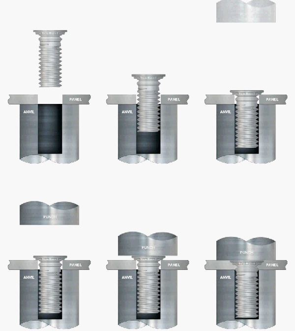
The following are the processing requirements for press-riveting studs: Generally, sheets with a thickness less than 1mm are not used for press-riveting. The use of the press-riveting mold must be positioned correctly at the first attempt, ensuring all corners of the stud are fully embedded in the sheet, and they are flush with the component surface, providing good flatness of the sheet and perpendicularity with the stud.
As the S value of press-riveting screws is usually large, it’s easy for material extrusion to occur during press-riveting, leading to part deformation. When press-riveting stainless steel screws into stainless steel sheets, the tolerance of the screw’s outer diameter and hole size should be maintained within ±0.05mm.
(IV) Loose-proof press-riveting screws and their process requirements:
Loose-proof press-riveting screws are often used in places that need to be fastened and frequently disassembled and installed.
The processing requirements for loose-proof press-riveting screws are as follows: The use of the press-riveting mold must be positioned correctly at the first attempt, ensuring all corners of the screw are fully embedded in the sheet, and they are flush with the component surface, providing good flatness of the sheet and perpendicularity with the screw.
(V) Positioning Pin and Its Process Requirements
The fabrication requirements for the press riveted positioning pin are as follows: when the length of the positioning pin (L) is greater than 20mm, based on structural analysis and process standards, it is necessary to reinforce the positioning pin by brazing (spot welding at the round head) to prevent misalignment.
The use of the die during press riveting must be accurate and in place the first time, and the protruding portion of the positioning pin must be entirely embedded in the sheet metal, being flush with the surface of the components. This ensures the flatness of the sheet metal and a good perpendicularity with the positioning pin.
1. The riveting process involves the fastening of rivet nuts, screws, studs, and custom hardware rivets (such as guide pins, locating support columns, etc.), electrostatic hand bowl bases, and riveting wrenches.
2. Riveting near the edge of a product or the circumference of a hole can cause significant deformation. Based on the extent of deformation, the necessary measures (such as reshaping or grinding) should be taken to meet the dimensional and aesthetic requirements as per the design drawings.
3. After riveting, there must be no misalignment or offsetting. It is essential to ensure that the threads align concentrically with their corresponding holes.
4. The material, specifications, and model of the riveted parts must match those in the drawings. The use of incorrect specifications is not permitted.
5. After riveting, conspicuous deformation, protrusion, or indentation around the riveted parts is unacceptable. There must be no visible imprints or mold marks that cannot be concealed through surface treatment.
6. Riveted parts must not be loose or detached after riveting. Their firmness must be tested; the push-pull force and torque values must comply with the requirements specified by PEM for the riveted part specifications.
7. It is imperative to promptly verify whether the material and model specifications of the rivets used in the production line, as marked on the packaging, comply with the design drawings. Check for any mixed materials in the packaging.
8. After riveting, the threads of the riveted parts must pass inspection: the go/no-go gauges must function correctly.
