Attention all metalworking professionals! Are you tired of unexpected downtime due to perplexing error codes on your AMADA CNC Press Brake? Look no further! In this blog post, a seasoned mechanical engineering expert demystifies the most common alarm codes, providing clear explanations and practical troubleshooting solutions to keep your press brake running smoothly. Get ready to boost your productivity and minimize frustration with these invaluable insights!
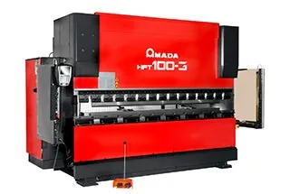
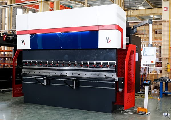
AMADA Press Brake Machine is a cost-effective equipment in the sheet metal processing plant due to its high bending precision, fast speed, and low number of faults.
However, when using the AMADA CNC Press Brake for the first time, the operator may not be familiar with the alarm code information. This is often due to incorrect operation, and some codes may indicate faults with the equipment.
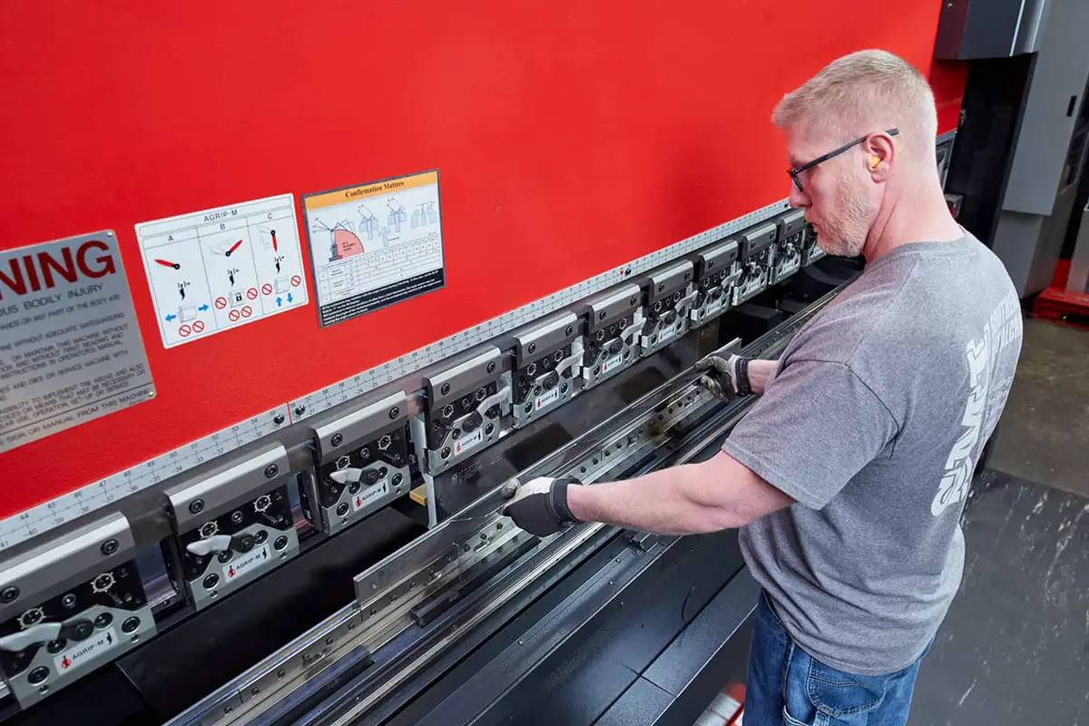
This post provides a list of error codes and their handling methods for AMADA CNC Press Brake to help you troubleshoot any problems with your press brake.
Let’s dive right into it.
Battery failure
Press the reset key.
ROM check sum error
Turn off the power, replace the ROM and turn on the power.
D / A digital to analog converter error (host side)
Shut down, repair and turn on the power supply.
D / A digital to analog converter error (slave side)
Shut down, repair and turn on the power supply.
PC ROM fault
Turn off the power, replace the ROM and turn on the power.
D-axis ROM fault
Turn off the power, replace the ROM and turn on the power.
D-axis ROM fault
Turn off the power, replace the motherboard and turn on the power.
Y-axis ROM fault
Turn off the power, replace the ROM and turn on the power.
Y-axis ROM fault
Turn off the power, replace the motherboard and turn on the power.
Z-axis ROM fault
Turn off the power, replace the ROM and turn on the power.
Z-axis ROM fault
Turn off the power, replace the motherboard and turn on the power.
D-axis cannot be sequenced
Shut down, turn off the power, repair and turn on the power.
Y-axis cannot be sequenced
Shut down, turn off the power, repair and turn on the power.
Z-axis cannot be sequenced
Shut down, turn off the power, repair and turn on the power.
D-axis parameter failure
Shut down, turn off the power, repair and turn on the power.
Y-axis parameter failure
Shut down, turn off the power, repair and turn on the power.
Z-axis parameter fault
Shut down, turn off the power, repair and turn on the power.
Relay fault
Shut down, turn off the power, repair and turn on the power.
Temperature switch of hydraulic motor
Find out the possible causes and deal with them. Reset the temperature switch and turn on the power.
Tonnage error
Shut down, turn off the power, repair and turn on the power.
Main pressure too high
Find out the possible causes and handle them, and press the alarm reset key.
Air pressure drop
Find out the possible causes and handle them, and press the alarm reset key.
Uneven pressure
Find out the possible causes and handle them, and press the alarm reset key.
NC hardware emergency stop
Shut down, turn off the power, repair and turn on the power.
The protective cover is opened
Close the cover and press the alarm reset key.
Upper mold action failed
Shut down, turn off the power, repair and turn on the power.
Relay fault (1)
Turn off the power and then turn it on.
Relay fault (2)
Turn off the power and then turn it on.
Relay fault (3)
Turn off the power and then turn it on.
Relay fault (4)
Turn off the power and then turn it on.
Relay fault (5)
Turn off the power and then turn it on.
Relay fault (6)
Turn off the power and then turn it on.
Relay fault (7)
Turn off the power and then turn it on.
Relay fault (8)
Turn off the power and then turn it on.
Abnormal stop
Press the emergency open button to open the upper die and press the alarm reset key.
Message error (ladder detection)
Shut down, turn off the power, repair and turn on the power.
Message error (bndnc detection)
Message error (bndnc found)
Mmi-nc information error
Turn off the power and then turn it on.
CS1 – remote I / O information error
Shut down, turn off the power, repair and turn on the power.
NC temperature alarm
Turn off the power and cool.
Control panel temperature alarm
Turn off the power and cool.
EEPROM write overcurrent
Shut down, turn off the power, repair and turn on the power.
Parameter alarm & Shutdown
Turn off the power, repair and turn on the power.
System alarm
Shut down, turn off the power, repair and turn on the power.
WDT alarm
Shut down, turn off the power, repair and turn on the power.
Thermometer failure
Shut down, turn off the power, repair and turn on the power.
Pressure sensor failure
Shut down, turn off the power, repair and turn on the power.
Upper die lifting failed
Shut down, turn off the power, repair and turn on the power.
Upper module return failed
Turn off the power, find out the possible causes and deal with them, and press the alarm reset key.
M1AT (Main) fault
Turn off the power and then turn it on.
M1AT (Times) fault
Turn off the power and then turn it on.
Abnormal stop (M1 tilt abnormal stop)
Shut down, turn off the power, repair and turn on the power.
Abnormal stop (2) (MPC abnormal stop)
Shut down, turn off the power, repair and turn on the power.
Abnormal stop (3) (M1 deceleration abnormal stop)
Shut down, turn off the power, repair and turn on the power.
Abnormal stop (4) (abnormal close detection)
Shut down, turn off the power, repair and turn on the power.
Relay fault (10) (foot switch error)
Shut down, turn off the power, repair and turn on the power.
Relay fault (11) (abnormal stop error)
Shut down, turn off the power, repair and turn on the power.
Relay fault (12) (sending off signal error)
Shut down, turn off the power, repair and turn on the power.
Relay fault (13) (M1 sends open signal error)
Shut down, turn off the power, repair and turn on the power.
Relay failure (14) (alternative safety device invalid error)
Shut down, turn off the power, repair and turn on the power.
Relay fault (15) (close start MPC error)
Shut down, turn off the power, repair and turn on the power.
Relay fault (16) (maximum closing limit on error)
Shut down, turn off the power, repair and turn on the power.
Relay failure (17) (causing abnormal fr bending (number of blows)
Shut down, turn off the power, repair and turn on the power.
Relay fault (18) (FS1a error)
Shut down, turn off the power, repair and turn on the power.
Relay fault (19) (fs1b error)
Shut down, turn off the power, repair and turn on the power.
Relay fault (20) (prevent reoperation error)
Shut down, turn off the power, repair and turn on the power.
Relay fault (21) (operation error)
Shut down, turn off the power, repair and turn on the power.
Relay fault (22) (closing start Ka error)
Shut down, turn off the power, repair and turn on the power.
Relay fault (23) (maximum closing limit storage error)
Shut down, turn off the power, repair and turn on the power.
Relay fault (24) (full up mode error)
Shut down, turn off the power, repair, and turn on the power.
Relay fault (25) (closing M1 error)
Shut down, turn off the power, repair, and turn on the power.
Relay fault (26) (closing LSV error)
Shut down, turn off the power, repair, and turn on the power.
Relay fault (27) (normal action relay error)
Shut down, turn off the power, repair, and turn on the power.
Relay fault (28) (initialization detection error)
Shut down, turn off the power, repair, and turn on the power.
Safety valve error
Press alarm reset.
Pre injection pilot valve error
Press alarm reset.
Transmission valve error
Press alarm reset.
Internal logic error 1 (unable to count SD timer)
Reset the power supply.
Internal logic error 1 (SD position output when SD timer counts)
Press the alarm reset key.
Internal logic error 1 (start condition is different from valve condition)
Reset the power supply.
Raster error
Press the alarm reset key.
Float valve error
Move the upper die to its opening limit position, and then inject oil again.
The upper die and tension bar may have been twisted
Move the upper die to its opening limit position and reset the alarm. If the l-axis tilts, repair and restart the system.
Upper mold locking movement error
Repair and reset the power supply.
Replace the filter element
If blocked, replace the element.
Action gain change error
Leakage error
Shut down, turn off the power, repair and turn on the power.
Leakage error
Shut down, turn off the power, repair and turn on the power.
Filter blockage alarm
The signal line may be disconnected. Turn off the power, repair and turn on the power.
CS1 abnormal stop circuit fault (remote I / O)
Shut down, turn off the power, repair and turn on the power.
NC abnormal stop circuit fault 1
Shut down, turn off the power, repair and turn on the power.
Abnormal gain detection circuit fault 1
Shut down, turn off the power, repair and turn on the power.
CS1 abnormal stop circuit fault 1
Shut down, turn off the power, repair and turn on the power.
Tilt detection circuit fault 1
Shut down, turn off the power, repair and turn on the power.
CS1 abnormal stop circuit fault 2
Shut down, turn off the power, repair and turn on the power.
Restart to prevent circuit failure
Shut down, turn off the power, repair and turn on the power.
Abnormal gain detection circuit fault 2
Shut down, turn off the power, repair and turn on the power.
NC abnormal stop circuit fault 2
Shut down, turn off the power, repair and turn on the power.
Tilt detection circuit fault 2
Shut down, turn off the power, repair and turn on the power.
Fu1 (linear servo amplifier power fuse) is off
Replace fuse 1 and reset the power supply.
Fu2 (AC100V power fuse) is off
Replace fuse 2 and reset the power supply.
Fu2 (DC24V power fuse) is off
Find out the cause, replace fuse 2 and reset the power supply.
Fu3 (Z-axis brake fuse) is off
Replace fuse 3 and reset the power supply.
Fu3 (AC100V power fuse) is off
Find out the cause, replace fuse 3 and reset the power supply.
Fu5 (DC24V power fuse) is off
Replace fuse 5 and reset the power supply.
Fu5 (DC24V power fuse) is off
Find out the cause, replace fuse 5 and reset the power supply.
Fu (valve controller power fuse) is off
Replace fuse 6 and reset the power supply.
Fu4 (Z-axis brake fuse) is off
Find out the cause, replace fuse 4 and reset the power supply.
D1 – abnormal pressure on shaft rod
The hydraulic system may have broken. Turn off the power, repair and then power on.
D2 – abnormal pressure on shaft rod
The hydraulic system may have broken. Turn off the power, repair and then power on.
D1 – abnormal logic pressure on shaft rod
The hydraulic system may have broken. Turn off the power, repair and then power on.
D2 – abnormal logic pressure on shaft rod
The hydraulic system may have broken. Turn off the power, repair and then power on.
Ramlocklimit error.
Shut down, repair and turn on the power supply.
Axis d1abs encoder initialization error
Shut down, repair and turn on the power supply.
Axis d1abs encoder initialization error
Shut down, repair and turn on the power supply.
Parameter changes are prohibited before resetting the origin
Reset the power supply.
The beam is opened during ABS encoder loading
Reset the power supply.
ABS encoder error 1
Shut down, repair and turn on the power supply.
ABS encoder error 2
Shut down, repair and turn on the power supply.
Encoder data alarm (servo amplifier alarm a.84)
Shut down, repair and turn on the power supply.
Encoder battery alarm (servo amplifier alarm a.83)
Replace the battery (servo amplifier).
Encoder summation check alarm (servo amplifier alarm a.82)
Reset the power supply.
Encoder backup alarm (servo amplifier alarm a.81)
Reset absolute origin.
Valve action error
Turn off the power and then turn it on. (repair required).
High voltage signal error
The ball joint or pressure sensor may have been disconnected. Turn off the power, repair and turn on the power.
CC shaft overtravel (-)
Move the CC axis in the (+) direction and press the alarm reset key.
D-axis overtravel (+)
Move the d-axis in the (-) direction and press the alarm reset key.
D-axis tilt
Fix and press the alarm reset key.
L1 – shaft overtravel (+)
Move L1 axis in (-) direction and press alarm reset key.
L2 – shaft overtravel (+)
Move the L2 axis in the (-) direction and press the alarm reset key.
L-axis tilt
Turn off the power, straighten the reverse travel limiter to balance it with the base, and turn on the power again.
Handwheel encoder error.
Turn off the power and then turn it on.
Yr axis super program (+)
Move the yr axis in the (-) direction and press the alarm reset key.
YL axis program (-)
Move the YL axis in the (+) direction and press the alarm reset key.
ZL axis program (-)
Move the ZL axis in the (+) direction and press the alarm reset key.
Zr axis program (-)
Move the Zr axis in the (+) direction and press the alarm reset key.
CC axis servo failure
Turn off the power, find out the possible causes, deal with them and turn on the power.
L1 axis servo failure
Turn off the power, find out the possible causes, deal with them and turn on the power.
L2 axis servo failure
Turn off the power, find out the possible causes, deal with them and turn on the power.
Y-axis servo failure
Turn off the power, find out the possible causes, deal with them and turn on the power.
Z-axis servo failure
Turn off the power, find out the possible causes, deal with them and turn on the power.
D-axis encoder circuit fault
Turn off the power, replace the motherboard and turn on the power.
Y-axis encoder circuit fault
Turn off the power, replace the motherboard and turn on the power.
Z-axis encoder circuit fault
Turn off the power, replace the motherboard and turn on the power.
D1 axis high frequency alarm
Restart the system after inspection.
D2 axis high frequency alarm
Restart the system after inspection.
Y-axis automatic zero balance fault
Shut down, turn off the power, repair and turn on the power.
Z-axis automatic zero balance fault
Shut down, turn off the power, repair and turn on the power.
D1-axis encoder fault
Shut down, turn off the power, repair and turn on the power.
D2-axis encoder fault
Shut down, turn off the power, repair and turn on the power.
L1-axis encoder fault
Shut down, turn off the power, repair and turn on the power.
L2 axis encoder fault
Shut down, turn off the power, repair and turn on the power.
CC-axis encoder fault
Shut down, turn off the power, repair and turn on the power.
YL-axis encoder fault
Shut down, turn off the power, repair and turn on the power.
YR-axis encoder fault
Shut down, turn off the power, repair and turn on the power.
ZL-axis encoder fault
Shut down, turn off the power, repair and turn on the power.
ZR-axis encoder fault
Shut down, turn off the power, repair and turn on the power.
Timeout while positioning D1 axis
Press the alarm reset key. (repair required).
Timeout while positioning D2 axis
Press the alarm reset key. (repair required).
L1-axis position setting timeout
Press the alarm reset key. (maintenance required)
L2-axis position setting timeout
Press the alarm reset key. (maintenance required)
Timeout while positioning YL axis
Press the alarm reset key. (repair required).
Timeout when positioning yr axis
Press the alarm reset key. (repair required).
Timeout while positioning ZL axis
Press the alarm reset key. (repair required).
Timeout while positioning Zr axis
Press the alarm reset key. (repair required).
Too many L1 axis errors
Adjust the servo mechanism.
Too many errors in L2 axis
Adjust the servo mechanism.
Too many errors on CC axis
Adjust the servo mechanism.
Too many errors on d-axis
Shut down, turn off the power, repair and turn on the power.
D1 – shaft overtravel (+)
Move the D-axis in the (-) direction and press the alarm reset key.
D2 – shaft overtravel (+)
Move the d-axis in the (-) direction and press the alarm reset key.
ZL axis overtravel (+)
Move the Z-axis in the (-) direction and press the alarm reset key.
ZR axis overtravel (+)
Move the Z-axis in the (-) direction and press the alarm reset key.
No zero phase limit signal (D1 axis)
Turn off the power and then turn it on. (repair required).
No zero phase limit signal (D2 axis)
Turn off the power and then turn it on. (repair required).
No grid point (L1 axis)
Turn off the power and then turn it on. (repair required).
No grid point (L2 axis)
Turn off the power and then turn it on. (repair required).
No grid point (CC axis)
Turn off the power and then turn it on. (repair required).
No zero phase limit signal (YL axis)
Turn off the power and then turn it on. (repair required).
No zero phase limit signal (YR axis)
Turn off the power and then turn it on. (repair required).
No zero phase limit signal (ZL axis)
Turn off the power and then turn it on. (repair required).
No zero phase limit signal (ZR axis)
Turn off the power and then turn it on. (repair required).
No zero phase limit signal (PT axis)
Turn off the power and then turn it on. (repair required).
No zero phase limit signal (PW axis)
Turn off the power and then turn it on. (repair required).
Clearance along D-axis
Press the alarm reset key.
Clearance along l-axis
Press the alarm reset key.
Clearance along YZ axis
Press the alarm reset key.
The origin height has changed
Press the alarm reset key and reset the origin
The difference between left and right is too big
Turn off the power and then turn it on. (repair required).
Passedgoal exceeded the target
Turn off the power and then turn it on. (repair required).
D-axis command sequence failure
Turn off the power and then turn it on. (repair required).
D-axis super program (-)
Turn off the power and then turn it on.
D1 – shaft overtravel (-)
Turn off the power and then turn it on.
D2 – shaft overtravel (-)
Turn off the power and then turn it on.
Too many errors on D1-axis
Adjust the servo mechanism.
Too many errors on D2 axis
Adjust the servo mechanism.
Z1-axis servo failure
Turn off the power, check the servo amplifier and turn on the power.
Z2-axis servo failure
Turn off the power, check the servo amplifier and turn on the power.
D1-axis servo failure
Turn off the power, check the servo amplifier and turn on the power.
D2-axis servo failure
Turn off the power, check the servo amplifier and turn on the power.
Y1-axis servo failure
Turn off the power, check the servo amplifier and turn on the power.
Y2-axis servo failure
Turn off the power, check the servo amplifier and turn on the power.
Main coil fault
Turn off the power and then turn it on. (repair required).
YR-axis sequence fault
Press the alarm reset key.
ZL-axis sequence fault
Press the alarm reset key.
ZR- axis sequence fault
Press the alarm reset key.
PT-axis sequence fault
Press the alarm reset key.
PW-axis sequence fault
Press the alarm reset key.
L-axis movement timing fault
Press the alarm reset key.
YZ-axis movement timing fault
Press the alarm reset key.
D1 – too many errors on the axis (when stopped)
Adjust the servo mechanism.
Too many errors on D2-axis (at stop)
Adjust the servo mechanism.
D1 – too many errors on the axis (in motion)
Adjust the servo mechanism.
Too many errors on D2-axis (in motion)
Adjust the servo mechanism.
D1 – too many errors on the axis (combined)
Adjust the servo mechanism.
Too many errors on D2-axis (combined)
Adjust the servo mechanism.
Too many errors on Y1-axis
Adjust the servo mechanism.
Too many errors on Y2-axis
Adjust the servo mechanism.
Too many errors on Z1 -axis
Adjust the servo mechanism.
Too many errors on Z2- axis
Adjust the servo mechanism.
L1 -axis communication determined
Turn off the power and then turn it on.
L2- axis communication determined
Turn off the power and then turn it on.
Y1- axis communication determined
Turn off the power and then turn it on.
Y2- axis communication determined
Turn off the power and then turn it on.
Z1- axis communication determined
Turn off the power and then turn it on.
Z2-axis communication determined
Turn off the power and then turn it on.
7-axis communication determined
Turn off the power and then turn it on.
8-axis communication determined
Turn off the power and then turn it on.
9-axis communication determined
Turn off the power and then turn it on.
10 -axis communication determined
Turn off the power and then turn it on.
11- axis communication determined
Turn off the power and then turn it on.
Communication fault alarm
Turn off the power and then turn it on. (repair required).
External posture
Turn off the power and then turn it on. (repair required).
Overpressure
Turn off the power and then turn it on. (repair required).
Control power error
Turn off the power and then turn it on. (repair required).
The main power supply voltage decreases
Turn off the power and then turn it on.
Main power loss
Turn off the power and then turn it on.
Read write error
Turn off the power and then turn it on.
L1- axis power supply error
Turn off the power and then turn it on.
L2- axis power supply error
Turn off the power and then turn it on.
Y1- axis power supply error
Turn off the power and then turn it on.
Y2 -axis power supply error
Turn off the power and then turn it on.
Z1- axis power supply error
Turn off the power and then turn it on.
Z2- axis power supply error
Turn off the power and then turn it on.
7-axis power supply error
Turn off the power and then turn it on.
8-axis power supply error
Turn off the power and then turn it on.
9-axis power supply error
Turn off the power and then turn it on.
10- axis power supply error
Turn off the power and then turn it on.
11- axis power supply error
Turn off the power and then turn it on.
12- axis power supply error
Turn off the power and then turn it on.
L1 – shaft overload
Turn off the power and then turn it on.
L2- axis overload
Turn off the power and then turn it on.
Y1- axis overload
Turn off the power and then turn it on.
Y2- axis overload
Turn off the power and then turn it on.
Z1 – shaft overload
Turn off the power and then turn it on.
Z2 -axis overload
Turn off the power and then turn it on.
7-shaft overload (optional)
Turn off the power and then turn it on.
8-axis overload (optional)
Turn off the power and then turn it on.
9-axis overload (optional)
Turn off the power and then turn it on.
10 – shaft overload (optional)
Turn off the power and then turn it on.
11 – shaft overload (optional)
Turn off the power and then turn it on.
12 – shaft overload (optional)
Turn off the power and then turn it on.
L1-axis acceleration
Turn off the power and then turn it on.
L2 -axis acceleration
Turn off the power and then turn it on.
Y1 -axis acceleration
Turn off the power and then turn it on.
Y2- axis acceleration
Turn off the power and then turn it on.
Z1- axis acceleration
Turn off the power and then turn it on.
Z2 -axis acceleration
Turn off the power and then turn it on.
7-axis acceleration (optional)
Turn off the power and then turn it on.
8-axis acceleration (optional)
Turn off the power and then turn it on.
9-axis acceleration (optional)
Turn off the power and then turn it on.
10 – shaft acceleration (optional)
Turn off the power and then turn it on.
11 – shaft acceleration (optional)
Turn off the power and then turn it on.
12 – shaft acceleration (optional)
Turn off the power and then turn it on.
L1 -axis speed control abnormal
Turn off the power and then turn it on.
L2 -axis speed control abnormal
Turn off the power and then turn it on.
Y1- axis speed control abnormal
Turn off the power and then turn it on.
Y2 -axis speed control abnormal
Turn off the power and then turn it on.
Z1- axis speed control abnormal
Turn off the power and then turn it on.
Z2 -axis speed control abnormal
Turn off the power and then turn it on.
7-axis speed control abnormal (optional)
Turn off the power and then turn it on.
8-axis speed control abnormal (optional)
Turn off the power and then turn it on.
9-axis speed control abnormal (optional)
Turn off the power and then turn it on.
10 – abnormal shaft speed control (optional)
Turn off the power and then turn it on.

