Have you ever struggled with calculating the right bend allowance for your sheet metal projects? In this blog post, we’ll dive into the world of bend allowances and explore how to use a bend allowance calculator to streamline your workflow. As an experienced mechanical engineer, I’ll share my insights and break down the concepts behind this handy tool. Get ready to learn how to achieve precise bends and save time on your next project!

Bend allowance is a fundamental concept in sheet metal fabrication, essential for achieving accurate dimensions in bent metal parts. It accounts for the elongation of the material that occurs during the bending process, ensuring that the final dimensions of the part match the design specifications.
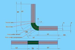
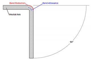
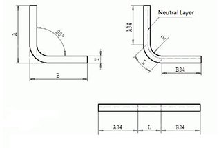
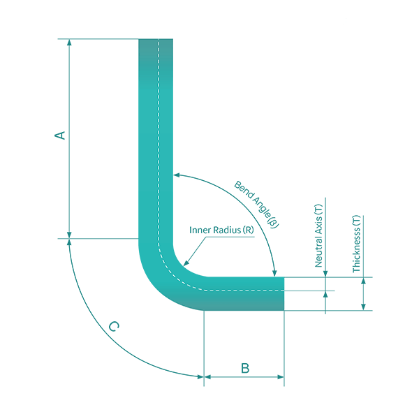
Bend allowance refers to the length of the neutral axis from the beginning to the end of the bend. The neutral axis is an imaginary line within the material that undergoes no compression or elongation during bending. This calculation is crucial for determining the flat pattern layout of a sheet metal part, as it considers the material’s deformation when bent.
Accurate calculation of bend allowance is vital for several reasons. First, it ensures that the final dimensions of the bent part match the design specifications. Additionally, it helps in minimizing material waste by accurately predicting the amount of material needed. This reduction in waste leads to cost savings in the manufacturing process by reducing the risk of errors and rework.
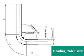
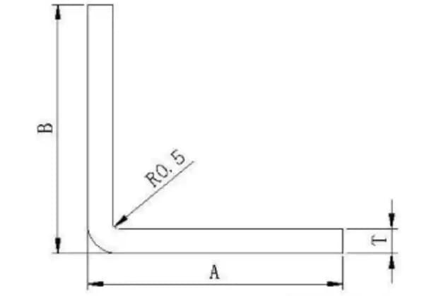
Several factors influence the bend allowance. Material thickness (T) plays a significant role, as thicker materials have different bend characteristics compared to thinner materials. The bend angle (θ), typically measured as the complementary angle, affects how much the material will stretch. The inside radius (r) of the bend on the inside of the material also impacts the calculation. Lastly, the K-factor (K), a material-specific constant representing the ratio between the material thickness and the neutral axis, is crucial.
The bend allowance can be calculated using the following formula:
Where:
Consider a sheet metal part with the following properties:
Using the bend allowance formula:
This calculation provides the bend allowance needed to develop the flat pattern of the sheet metal part accurately.
For new press brake operators who may not be familiar with the intricacies of calculating bend allowance, a bend allowance calculator can be an invaluable tool. This calculator simplifies the process, ensuring accurate results and making daily work more efficient.
Online bend allowance calculators simplify the process by allowing users to input parameters such as material thickness, bend angle, inside radius, and K-factor. These calculators then compute the bend allowance and sometimes the bend deduction, ensuring accurate sheet metal fabrication. By using these tools, manufacturers can save time and reduce the risk of errors in their calculations.
To use the bend allowance calculator effectively, operators need to input the following parameters:
Related calculator:
Further reading:
Bend allowance is the additional material length required when bending sheet metal to achieve the desired final dimensions after forming. It compensates for the stretching and compression that occurs in the material during the bending process.The bend allowance varies based on several factors:
Bend allowance values are typically determined through a combination of empirical data, mathematical calculations, and practical experience. Experienced sheet metal designers and engineers have developed bend allowance tables and formulas over years of repeated testing and verification.
By using the appropriate bend allowance formula or referring to reliable bend allowance charts, designers can accurately calculate the flat pattern dimensions of a sheet metal part that will yield the desired final bent dimensions. This is crucial for creating accurate flat patterns and ensuring that the bent part fits and functions as intended.
Bend allowance and bend deduction calculations are essential methods used to determine the length of sheet metal raw materials in their flat form, ensuring the desired size of the bent part is achieved. Understanding these calculations is crucial for precision in sheet metal fabrication.
Bend Allowance Calculation Method:
The bend allowance (BA) is the amount of material that is added to the total length of the flat sheet to account for the material that will be used in the bend.
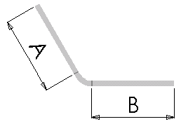
The following equation is used to determine the total flattening length when the bend allowance value is used:
Lt = A + B + BA
Where:
Bend Deduction Calculation Method:
The bend deduction (BD) is the amount of material that is subtracted from the total length of the flat sheet to account for the material that will be used in the bend.
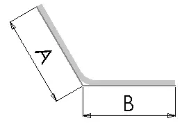
The following equation is used to determine the total flattening length when using the bend deduction value:
Lt = A + B – BD
Where:
In addition to the bend allowance and bend deduction methods, other techniques can be used to determine the flat length of sheet metal raw materials. These include:
| Material | Thickness | Bending angle | V opening | Inner radius | Bends Allowance |
|---|---|---|---|---|---|
| SPCC | 0.5 | 90 | V4 | 0.5 | 0.95 |
| 100 | 0.73 | ||||
| 135 | 0.3 | ||||
| 175 | 0.03 | ||||
| SPCC | 0.5 | 90 | V5 | 0.5 | 1.03 |
| 100 | 0.79 | ||||
| 135 | 0.33 | ||||
| 175 | 0.03 | ||||
| SPCC | 0.5 | 90 | V6 | 0.5 | 1.1 |
| 100 | 0.85 | ||||
| 135 | 0.35 | ||||
| 175 | 0.03 | ||||
| SPCC | 0.6 | 90 | V4 | 0.5 | 1.08 |
| 100 | 0.83 | ||||
| 135 | 0.35 | ||||
| 175 | 0.03 | ||||
| SPCC | 0.6 | 90 | V5 | 0.5 | 1.15 |
| 100 | 0.89 | ||||
| 135 | 0.37 | ||||
| 175 | 0.03 | ||||
| SPCC | 0.6 | 90 | V6 | 0.5 | 1.23 |
| 100 | 0.95 | ||||
| 135 | 0.39 | ||||
| 175 | 0.03 | ||||
| SPCC | 0.8 | 90 | V6 | 0.5 | 1.49 |
| 120 | 0.73 | ||||
| 135 | 0.47 | ||||
| 150 | 0.25 | ||||
| SPCC | 0.8 | 90 | V8 | 0 | 1.64 |
| 120 | 0.81 | ||||
| 135 | 0.52 | ||||
| 150 | 0.27 | ||||
| SPCC | 0.8 | 90 | V10 | 0 | 1.79 |
| 120 | 0.88 | ||||
| 135 | 0.57 | ||||
| 150 | 0.3 | ||||
| SPCC | 1 | 90 | V10 | 0 | 2.05 |
| 100 | 1.58 | ||||
| 120 | 1.01 | ||||
| 135 | 0.62 | ||||
| 175 | 0.06 | ||||
| SPCC | 1 | 90 | V8 | 0 | 1.9 |
| 100 | 1.47 | ||||
| 120 | 0.93 | ||||
| 135 | 0.6 | ||||
| 175 | 0.05 | ||||
| SPCC | 1 | 90 | V6 | 0 | 1.74 |
| 100 | 1.35 | ||||
| 120 | 0.86 | ||||
| 135 | 0.56 | ||||
| 175 | 0.05 | ||||
| SPCC | 1.2 | 90 | V10 | 1.4 | 2.31 |
| 100 | 1.78 | ||||
| 120 | 1.13 | ||||
| 135 | 0.73 | ||||
| 175 | 0.06 | ||||
| SPCC | 1.2 | 90 | V8 | 1.4 | 2.15 |
| 100 | 1.66 | ||||
| 120 | 1.06 | ||||
| 135 | 0.69 | ||||
| 175 | 0.06 | ||||
| SPCC | 1.2 | 90 | V6 | 1.4 | 2 |
| 100 | 1.55 | ||||
| 120 | 0.98 | ||||
| 135 | 0.64 | ||||
| 175 | 0.05 | ||||
| SPCC | 1.5 | 90 | V6 | 1.7 | 2.36 |
| 100 | 1.82 | ||||
| 120 | 1.16 | ||||
| 135 | 0.75 | ||||
| 175 | 0.06 | ||||
| SPCC | 1.5 | 90 | V12 | 1.7 | 2.8 |
| 100 | 2.17 | ||||
| 120 | 1.38 | ||||
| 135 | 0.89 | ||||
| 175 | 0.08 | ||||
| SPCC | 1.5 | 90 | V10 | 1.7 | 2.65 |
| 100 | 2.05 | ||||
| 120 | 1.31 | ||||
| 135 | 0.85 | ||||
| 175 | 0.07 | ||||
| SPCC | 1.5 | 90 | V8 | 1.7 | 2.5 |
| 100 | 1.94 | ||||
| 120 | 1.23 | ||||
| 135 | 0.8 | ||||
| 175 | 0.07 | ||||
| SPCC | 2 | 90 | V10 | 2 | 3.29 |
| 100 | 2.54 | ||||
| 120 | 1.62 | ||||
| 135 | 1.05 | ||||
| 175 | 0.09 | ||||
| SPCC | 2 | 90 | V12 | 2 | 3.44 |
| 100 | 2.66 | ||||
| 120 | 1.69 | ||||
| 135 | 1.1 | ||||
| 175 | 0.09 | ||||
| SPCC | 2.5 | 90 | V18 | 3.03 | 4.6 |
| 100 | 3.56 | ||||
| 120 | 2.26 | ||||
| 135 | 1.47 | ||||
| 175 | 0.12 | ||||
| SPCC | 2.5 | 90 | V12 | 3.03 | 4.15 |
| 100 | 3.21 | ||||
| 120 | 2.04 | ||||
| 135 | 1.32 | ||||
| 175 | 0.11 | ||||
| SPCC | 2.5 | 90 | V10 | 3.03 | 4 |
| 100 | 3.09 | ||||
| 120 | 1.97 | ||||
| 135 | 1.28 | ||||
| 175 | 0.11 | ||||
| SPCC | 3 | 90 | V18 | 3.133.13 | 5.22 |
| 100 | 4.03 | ||||
| 120 | 2.57 | ||||
| 135 | 1.66 | ||||
| 175 | 0.14 | ||||
| SPCC | 3 | 90 | V12 | 3.13 | 4.78 |
| 100 | 3.69 | ||||
| 120 | 2.35 | ||||
| 135 | 1.52 | ||||
| 175 | 0.13 | ||||
| SPCC | 3 | 90 | V10 | 3.13 | 4.63 |
| 100 | 3.58 | ||||
| 120 | 2.28 | ||||
| 135 | 1.48 | ||||
| 175 | 0.13 |
| Material | Thickness | Bending angle | V opening | Inner radius | Bends Allowance |
|---|---|---|---|---|---|
| SUS | 0.5 | 90 | 4 | 0.6 | 1.04 |
| 100 | 0.79 | ||||
| 120 | 0.48 | ||||
| 135 | 0.3 | ||||
| 175 | 0.04 | ||||
| SUS | 0.5 | 90 | 5 | 0.6 | 1.15 |
| 100 | 0.88 | ||||
| 120 | 0.54 | ||||
| 135 | 0.33 | ||||
| 175 | 0.04 | ||||
| SUS | 0.5 | 90 | 6 | 0.6 | 1.27 |
| 100 | 1.13 | ||||
| 120 | 0.59 | ||||
| 135 | 0.37 | ||||
| 175 | 0.04 | ||||
| SUS | 0.6 | 90 | 4 | 0.6 | 1.16 |
| 100 | 0.88 | ||||
| 120 | 0.54 | ||||
| 135 | 0.34 | ||||
| 175 | 0.04 | ||||
| SUS | 0.6 | 90 | 5 | 0.6 | 1.27 |
| 100 | 0.97 | ||||
| 120 | 0.59 | ||||
| 135 | 0.37 | ||||
| 175 | 0.04 | ||||
| SUS | 0.6 | 90 | 6 | 0.6 | 1.38 |
| 100 | 1.05 | ||||
| 120 | 0.64 | ||||
| 135 | 0.4 | ||||
| 175 | 0.05 | ||||
| SUS | 0.8 | 90 | 4 | 1.1 | 1.4 |
| 100 | 1.06 | ||||
| 120 | 0.65 | ||||
| 135 | 0.4 | ||||
| 175 | 0.05 | ||||
| SUS | 0.8 | 90 | 5 | 1.1 | 1.51 |
| 100 | 1.15 | ||||
| 120 | 0.7 | ||||
| 135 | 0.44 | ||||
| 175 | 0.05 | ||||
| SUS | 0.8 | 90 | 6 | 1.1 | 1.62 |
| 100 | 1.23 | ||||
| 120 | 0.75 | ||||
| 135 | 0.47 | ||||
| 175 | 0.06 | ||||
| SUS | 1 | 90 | 6 | 1.9 | 1.87 |
| 100 | 1.42 | ||||
| 120 | 0.87 | ||||
| 135 | 0.54 | ||||
| 175 | 0.07 | ||||
| SUS | 1 | 90 | 8 | 1.9 | 2.1 |
| 100 | 1.6 | ||||
| 120 | 0.98 | ||||
| 135 | 0.61 | ||||
| 175 | 0.07 | ||||
| SUS | 1.2 | 90 | 6 | 1.6 | 2.1 |
| 100 | 1.59 | ||||
| 120 | 0.97 | ||||
| 135 | 0.61 | ||||
| 175 | 0.07 | ||||
| SUS | 1.2 | 90 | 8 | 1.6 | 2.32 |
| 100 | 1.76 | ||||
| 120 | 1.08 | ||||
| 135 | 0.67 | ||||
| 175 | 0.08 | ||||
| SUS | 1.2 | 90 | 10 | 1.6 | 2.54 |
| 100 | 1.93 | ||||
| 120 | 1.18 | ||||
| 135 | 0.74 | ||||
| 175 | 0.09 | ||||
| SUS | 1.5 | 90 | 8 | 2.1 | 2.68 |
| 100 | 2.03 | ||||
| 120 | 1.24 | ||||
| 135 | 0.77 | ||||
| 175 | 0.09 | ||||
| SUS | 1.5 | 90 | 10 | 2.1 | 2.9 |
| 100 | 2.2 | ||||
| 120 | 1.35 | ||||
| 135 | 0.84 | ||||
| 175 | 0.1 | ||||
| SUS | 2 | 90 | 10 | 3.49 | |
| 100 | 2.65 | ||||
| 120 | 1.62 | ||||
| 135 | 1.01 | ||||
| 175 | 0.12 | ||||
| SUS | 2 | 90 | 12 | 3.7 | |
| 100 | 2.82 | ||||
| 120 | 1.72 | ||||
| 135 | 1.07 | ||||
| 175 | 0.13 |
| Material | Thickness | Bending angle | V opening | Inner radius | Bends Allowance |
|---|---|---|---|---|---|
| SPHC | 1 | 90 | V10 | 1.86 | 2.05 |
| 100 | 1.58 | ||||
| 120 | 1.01 | ||||
| 135 | 0.62 | ||||
| 175 | 0.06 | ||||
| SPHC | 1 | 90 | V8 | 1.86 | 1.9 |
| 100 | 1.47 | ||||
| 120 | 0.93 | ||||
| 135 | 0.6 | ||||
| 175 | 0.05 | ||||
| SPHC | 1 | 90 | V6 | 1.86 | 1.74 |
| 100 | 1.35 | ||||
| 120 | 0.86 | ||||
| 135 | 0.56 | ||||
| 175 | 0.05 | ||||
| SPHC | 1.2 | 90 | V10 | 1.44 | 2.31 |
| 100 | 1.78 | ||||
| 120 | 1.13 | ||||
| 135 | 0.73 | ||||
| 175 | 0.06 | ||||
| SPHC | 1.2 | 90 | V8 | 1.44 | 2.15 |
| 100 | 1.66 | ||||
| 120 | 1.06 | ||||
| 135 | 0.69 | ||||
| 175 | 0.06 | ||||
| SPHC | 1.2 | 90 | V6 | 1.44 | 2 |
| 100 | 1.55 | ||||
| 120 | 0.98 | ||||
| 135 | 0.64 | ||||
| 175 | 0.05 | ||||
| SPHC | 1.5 | 90 | V12 | 1.74 | 2.8 |
| 100 | 2.17 | ||||
| 120 | 1.38 | ||||
| 135 | 0.89 | ||||
| 175 | 0.08 | ||||
| SPHC | 1.5 | 90 | V10 | 1.74 | 2.65 |
| 100 | 2.05 | ||||
| 120 | 1.31 | ||||
| 135 | 0.85 | ||||
| 175 | 0.07 | ||||
| SPHC | 1.5 | 90 | V8 | 1.74 | 2.5 |
| 100 | 1.94 | ||||
| 120 | 1.23 | ||||
| 135 | 0.8 | ||||
| 175 | 0.07 | ||||
| SPHC | 2 | 90 | V12 | 2.01 | 3.44 |
| 100 | 2.66 | ||||
| 120 | 1.69 | ||||
| 135 | 1.1 | ||||
| 175 | 0.09 | ||||
| SPHC | 2 | 90 | V10 | 2.01 | 3.29 |
| 100 | 2.54 | ||||
| 120 | 1.62 | ||||
| 135 | 1.05 | ||||
| 175 | 0.09 | ||||
| SPHC | 2.5 | 90 | V18 | 3 | 4.6 |
| 100 | 3.25 | ||||
| 120 | 2.26 | ||||
| 135 | 1.47 | ||||
| 175 | 0.12 | ||||
| SPHC | 2.5 | 90 | V12 | 3 | 4.15 |
| 100 | 3.21 | ||||
| 120 | 2.04 | ||||
| 135 | 1.32 | ||||
| 175 | 0.11 | ||||
| SPHC | 2.5 | 90 | V10 | 3 | 4 |
| 100 | 3.09 | ||||
| 120 | 1.97 | ||||
| 135 | 1.28 | ||||
| 175 | 0.11 | ||||
| SPHC | 3 | 90 | V18 | 3.1 | 5.22 |
| 100 | 4.03 | ||||
| 120 | 2.57 | ||||
| 135 | 1.66 | ||||
| 175 | 0.14 | ||||
| SPHC | 3 | 90 | V12 | 3.1 | 4.78 |
| 100 | 3.69 | ||||
| 120 | 2.35 | ||||
| 135 | 1.52 | ||||
| 175 | 0.13 | ||||
| SPHC | 3 | 90 | V10 | 3.1 | 4.63 |
| 100 | 3.58 | ||||
| 120 | 2.28 | ||||
| 135 | 1.48 | ||||
| 175 | 0.13 |
| Material | Thickness | Bending angle | V opening | Inner radius | Bends Allowance |
|---|---|---|---|---|---|
| SECC | 1 | 90 | V10 | 1.9 | 2.05 |
| 100 | 1.58 | ||||
| 120 | 1.01 | ||||
| 135 | 0.62 | ||||
| 175 | 0.06 | ||||
| SECC | 1 | 90 | V8 | 1.9 | 1.9 |
| 100 | 1.47 | ||||
| 120 | 0.93 | ||||
| 135 | 0.6 | ||||
| 175 | 0.05 | ||||
| SECC | 1 | 90 | V6 | 1.9 | 1.74 |
| 100 | 1.35 | ||||
| 120 | 0.86 | ||||
| 135 | 0.56 | ||||
| 175 | 0.05 | ||||
| SECC | 1.2 | 90 | V10 | 1.4 | 2.31 |
| 100 | 1.78 | ||||
| 120 | 1.13 | ||||
| 135 | 0.73 | ||||
| 175 | 0.06 | ||||
| SECC | 1.2 | 90 | V8 | 1.4 | 2.15 |
| 100 | 1.66 | ||||
| 120 | 1.06 | ||||
| 135 | 0.69 | ||||
| 175 | 0.06 | ||||
| SECC | 1.2 | 90 | V6 | 1.4 | 2 |
| 100 | 1.55 | ||||
| 120 | 0.98 | ||||
| 135 | 0.64 | ||||
| 175 | 0.05 | ||||
| SECC | 1.5 | 90 | V12 | 1.7 | 2.8 |
| 100 | 2.17 | ||||
| 120 | 1.38 | ||||
| 135 | 0.89 | ||||
| 175 | 0.08 | ||||
| SECC | 1.5 | 90 | V10 | 1.7 | 2.65 |
| 100 | 2.05 | ||||
| 120 | 1.31 | ||||
| 135 | 0.85 | ||||
| 175 | 0.07 | ||||
| SECC | 1.5 | 90 | V8 | 1.7 | 2.5 |
| 100 | 1.94 | ||||
| 120 | 1.23 | ||||
| 135 | 0.8 | ||||
| 175 | 0.07 | ||||
| SECC | 2 | 90 | V12 | 2 | 3.44 |
| 100 | 2.66 | ||||
| 120 | 1.69 | ||||
| 135 | 1.1 | ||||
| 175 | 0.09 | ||||
| SECC | 2 | 90 | V10 | 2 | 3.29 |
| 100 | 2.54 | ||||
| 120 | 1.62 | ||||
| 135 | 1.05 | ||||
| 175 | 0.09 | ||||
| SECC | 2.5 | 90 | V18 | 3.03 | 4.6 |
| 100 | 3.56 | ||||
| 120 | 2.26 | ||||
| 135 | 1.47 | ||||
| 175 | 0.12 | ||||
| SECC | 2.5 | 90 | V12 | 3.03 | 4.15 |
| 100 | 3.21 | ||||
| 120 | 2.01 | ||||
| 135 | 1.32 | ||||
| 175 | 0.11 | ||||
| SECC | 2.5 | 90 | V10 | 3.03 | 4 |
| 100 | 3.09 | ||||
| 120 | 1.97 | ||||
| 135 | 1.28 | ||||
| 175 | 0.11 | ||||
| SECC | 3 | 90 | V18 | 3.13 | 5.22 |
| 100 | 4.03 | ||||
| 120 | 2.57 | ||||
| 135 | 1.66 | ||||
| 175 | 0.14 | ||||
| SECC | 3 | 90 | V12 | 3.13 | 1.78 |
| 100 | 3.69 | ||||
| 120 | 2.35 | ||||
| 135 | 1.52 | ||||
| 175 | 0.13 | ||||
| SECC | 3 | 90 | V10 | 3.13 | 4.63 |
| 100 | 3.58 | ||||
| 120 | 2.28 | ||||
| 135 | 1.48 | ||||
| 175 | 0.13 |
| Material | Thickness | Bending angle | V opening | Inner radius | Bends Allowance |
|---|---|---|---|---|---|
| AL | 0.8 | 90 | 4 | 0.6 | 1.15 |
| 100 | 0.81 | ||||
| 120 | 0.5 | ||||
| 135 | 0.36 | ||||
| 175 | 0.03 | ||||
| AL | 0.8 | 90 | 5 | 0.6 | 1.2 |
| 100 | 0.85 | ||||
| 120 | 0.52 | ||||
| 135 | 0.37 | ||||
| 175 | 0.03 | ||||
| AL | 0.8 | 90 | 6 | 0.6 | 1.25 |
| 100 | 0.88 | ||||
| 120 | 0.54 | ||||
| 135 | 0.39 | ||||
| 175 | 0.03 | ||||
| AL | 1 | 90 | 6 | 0.6 | 1.49 |
| 100 | 1.05 | ||||
| 120 | 6.5 | ||||
| 135 | 0.46 | ||||
| 175 | 0.04 | ||||
| AL | 1 | 90 | 8 | 0.6 | 1.59 |
| 100 | 1.13 | ||||
| 120 | 0.69 | ||||
| 135 | 0.5 | ||||
| 175 | 0.04 | ||||
| AL | 1.2 | 90 | 6 | 0.9 | 1.73 |
| 100 | 1.22 | ||||
| 120 | 0.75 | ||||
| 135 | 0.54 | ||||
| 175 | 0.04 | ||||
| AL | 1.2 | 90 | 8 | 0.9 | 1.82 |
| 100 | 1.29 | ||||
| 120 | 0.79 | ||||
| 135 | 0.57 | ||||
| 175 | 0.05 | ||||
| AL | 1.5 | 90 | 8 | 1.2 | 2.18 |
| 100 | 1.54 | ||||
| 120 | 0.95 | ||||
| 135 | 0.68 | ||||
| 175 | 0.06 | ||||
| AL | 1.5 | 90 | 10 | 1.2 | 2.28 |
| 100 | 1.61 | ||||
| 120 | 0.99 | ||||
| 135 | 0.71 | ||||
| 175 | 0.06 | ||||
| AL | 1.5 | 90 | 12 | 1.2 | 2.38 |
| 100 | 1.68 | ||||
| 120 | 1.03 | ||||
| 135 | 0.74 | ||||
| 175 | 0.06 | ||||
| AL | 2 | 90 | 14 | 1.6 | 3.07 |
| 100 | 2.17 | ||||
| 120 | 1.3 | ||||
| 135 | 0.93 | ||||
| 175 | 0.08 | ||||
| AL | 2 | 90 | 12 | 1.6 | 2.98 |
| 100 | 2.11 | ||||
| 120 | 1.34 | ||||
| 135 | 0.95 | ||||
| 175 | 0.08 | ||||
| AL | 2 | 90 | 18 | 1.6 | 3.25 |
| 100 | 2.3 | ||||
| 120 | 1.42 | ||||
| 135 | 1.01 | ||||
| 175 | 0.08 | ||||
| AL | 2.5 | 90 | 18 | 2.4 | 3.89 |
| 100 | 2.75 | ||||
| 120 | 1.7 | ||||
| 135 | 1.21 | ||||
| 175 | 0.1 | ||||
| AL | 3 | 90 | 18 | 2.5 | 4.5 |
| 100 | 3.18 | ||||
| 120 | 1.96 | ||||
| 135 | 1.4 | ||||
| 175 | 0.1 | ||||
| AL | 3.2 | 90 | 18 | 2.5 | 4.74 |
| 100 | 3.35 | ||||
| 120 | 2.06 | ||||
| 135 | 1.47 | ||||
| 175 | 0.12 | ||||
| AL | 4 | 90 | 40 | 4.6 | 6.77 |
| 100 | 4.79 | ||||
| 120 | 2.95 | ||||
| 135 | 2.11 | ||||
| 175 | 0.17 | ||||
| AL | 6.8 | 90 | 800 | 9.4 | 12.09 |
| 100 | 8.55 | ||||
| 120 | 5.27 | ||||
| 135 | 3.76 | ||||
| 175 | 0.31 |
The K-factor is a crucial coefficient in sheet metal fabrication, representing the relative position of the neutral axis within the thickness of the material. The neutral axis is the imaginary plane within the material where no compression or tension occurs during the bending process. The K-factor is calculated as the ratio of the distance from the inner surface to the neutral axis to the total thickness of the material. Understanding the K-factor is essential for accurate bend allowance calculations, ensuring the precision of the final dimensions of bent parts.
The K-factor directly influences the bend allowance, which is the additional length of material needed to accommodate the bend. The bend allowance formula, which typically includes the bend angle, inside radius, material thickness, and K-factor, is:
where ( BA ) is the bend allowance, ( θ ) is the bend angle in radians, ( r ) is the inside radius, ( K ) is the K-factor, and ( T ) is the material thickness. This formula highlights the importance of the K-factor in ensuring that the bend allowance is accurately calculated, which is critical for achieving precise part dimensions and reducing material waste.
The K-factor is not a constant value and varies depending on several factors, including the properties of the material, the bending method, the bend radius, and the bend angle. Different materials and bending conditions will result in different K-factor values, typically ranging between 0.3 and 0.5. For instance, a material with high ductility may have a different K-factor compared to a more brittle material, influencing the bend allowance and, consequently, the final dimensions of the part.
To accurately calculate bend allowance and bend deduction, start by collecting the following parameters:
The bend allowance accounts for the additional length of material required to accommodate the bend. Use the bend allowance formula to determine this value:
1. Convert Bend Angle to Radians:
2. Apply the Bend Allowance Formula:
Next, determine the outside setback, which is important for calculating bend deduction. The formula for OSSB is:
Convert Bend Angle to Radians:
Apply the Outside Setback Formula:
Finally, use the outside setback and bend allowance to determine the bend deduction, which is crucial for achieving accurate dimensions in sheet metal fabrication:
Apply the Bend Deduction Formula:
Understanding the significance of each parameter is vital for successful bending operations. The K-factor, for instance, influences how much material is needed for the bend, while the bend allowance ensures the material will fit correctly after bending. Additionally, it is essential to account for spring back, a phenomenon where the metal returns slightly to its original shape after bending, which may necessitate overbending the material.
By following these steps and carefully considering each parameter, you can accurately calculate the bend allowance and bend deduction necessary for precise sheet metal fabrication.


