Have you ever pondered the importance of bend radius in mechanical design? In this article, we’ll explore this crucial concept and its impact on material integrity. Drawing from the expertise of seasoned engineers, we’ll provide valuable insights and guidelines to help you optimize your designs. Get ready to discover the secrets of successful bending and take your projects to the next level!
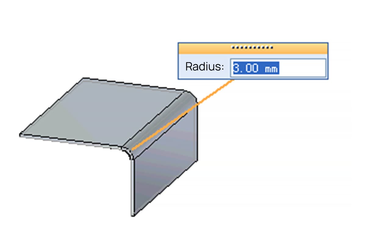
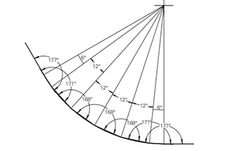
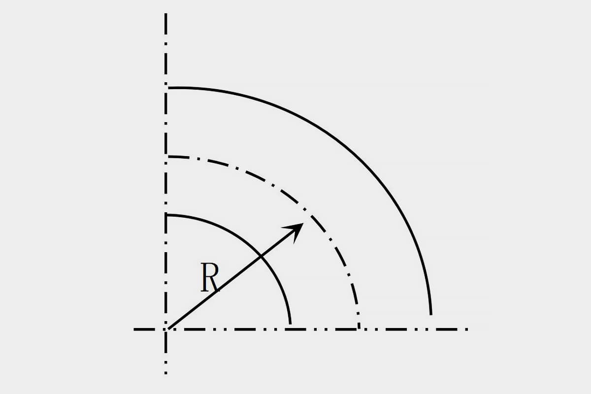
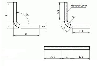
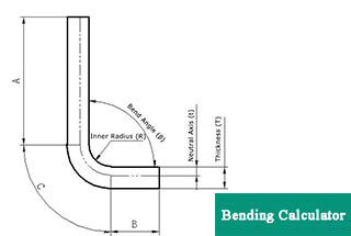
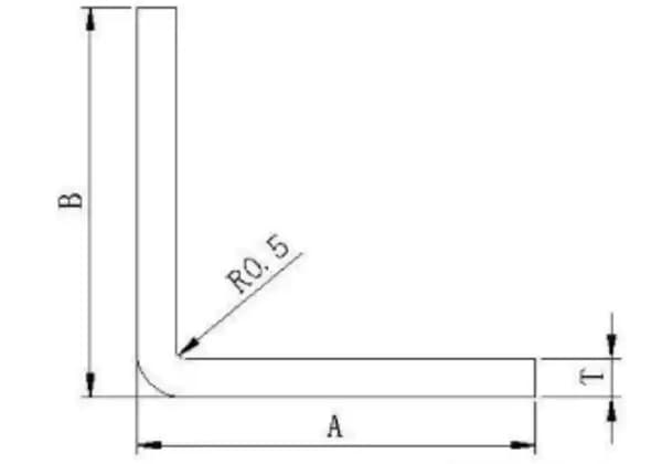
The bend radius refers to the inner radius of curvature in a bent metal part, where ‘t’ represents the material thickness. This parameter is crucial in sheet metal fabrication and structural design.
During the bending process, the material undergoes significant stress distribution. The outer layer of the bend experiences tensile stress and stretches, while the inner layer compresses. The severity of this deformation is inversely proportional to the bend radius; a smaller inner radius results in more extreme material stretching and compression for a given material thickness.
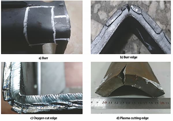
If the tensile stress on the outer bend surface exceeds the material’s ultimate tensile strength, it can lead to cracking or fracture. Consequently, the structural design of bent components should carefully consider the minimum allowable bend radius to prevent material failure.

The minimum bend radius varies depending on the material properties, particularly its ductility and work hardening characteristics. Here are some guidelines for common materials used in metal fabrication:
It’s important to note that these are general guidelines, and factors such as grain orientation, surface finish, and bending direction relative to the rolling direction can influence the actual minimum bend radius. In precision applications or when working with critical components, it’s advisable to conduct bending tests or consult material-specific data sheets for more accurate values.
| Item | Material | Thickness | Inside R | Die | Punch | ||
| Radius | V Width | Radius | Angle | ||||
| 1 | SPCC/SECC/SGCC | 0.8 | 1.3 | 0.5 | 8 | 0.2 | 88° |
| 2 | SPCC/SECC/SGCC | 0.9 | 1.3 | 0.5 | 6 | 0.2 | 88° |
| 3 | SPCC/SECC/SGCC | 1.0 | 1.3 | 0.5 | 8 | 0.2 | 88° |
| 4 | SPCC/SECC/SGCC | 1.2 | 1.0 | 0.4 | 6 | 0.2 | 88° |
| 5 | SPCC/SECC/SGCC | 1.2 | 1.3 | 0.5 | 8 | 0.2 | 88° |
| 6 | SPCC/SECC/SGCC | 1.5 | 1.3 | 0.5 | 8 | 0.2 | 88° |
| 7 | SPCC/SECC/SGCC | 1.6 | 1.3 | 0.5 | 8 | 0.6 | 88° |
| 8 | SPCC/SECC/SGCC | 1.8 | 2.0 | 0.8 | 12 | 0.6 | 88° |
| 9 | SPCC/SECC/SGCC | 2.0 | 2.0 | 0.8 | 12 | 0.6 | 88° |
| 10 | SPCC/SECC/SGCC | 2.3 | 2.0 | 0.8 | 12 | 0.6 | 88° |
| 11 | SPCC/SECC/SGCC | 2.5 | 2.6 | 0.8 | 16 | 0.6 | 88° |
| 12 | SPCC/SECC/SGCC | 3.0 | 2.6 | 0.8 | 16 | 0.6 | 88° |
| 13 | SPCC/SECC/SGCC | 4.0 | 4.0 | 0.8 | 25 | 0.6 | 88° |
| 14 | SPHC | 2.3 | 2.6 | 0.8 | 16 | 0.6 | 88° |
| 15 | SPHC | 3.2 | 2.6 | 0.8 | 16 | 0.6 | 88° |
| 16 | SPHC | 4.2 | 4.0 | 0.8 | 25 | 0.6 | 88° |
| 17 | SPHC | 4.8 | 4.0 | 0.8 | 25 | 0.6 | 88° |
| 18 | AL5052-H32 | 0.8 | 1.3 | 0.5 | 6 | 0.2 | 88° |
| 19 | AL5052-H32 | 1.0 | 1.3 | 0.5 | 8 | 0.2 | 88° |
| 20 | AL5052-H32 | 1.2 | 1.3 | 0.5 | 8 | 0.2 | 88° |
| 21 | AL5052-H32 | 1.5 | 1.3 | 0.5 | 8 | 0.2 | 88° |
| 22 | AL5052-H32 | 1.6 | 1.3 | 0.5 | 8 | 0.6 | 88° |
| 23 | AL5052-H32 | 1.6 | 1.3 | 0.6 | 10 | 0.6 | 88° |
| 24 | AL5052-H32 | 2.0 | 2.0 | 0.8 | 12 | 0.6 | 88° |
| 25 | AL5052-H32 | 2.3 | 2.6 | 0.8 | 16 | 0.6 | 88° |
| 26 | AL5052-H32 | 2.5 | 2.6 | 0.5 | 16 | 0.6 | 88° |
| 27 | AL5052-H32 | 3.0 | 2.6 | 0.8 | 16 | 0.6 | 88° |
| 28 | AL5052-H32 | 3.2 | 2.6 | 0.8 | 16 | 0.6 | 88° |
| 29 | AL5052-H32 | 3.5 | 4.0 | 0.8 | 25 | 1.5 | 88° |
| 30 | AL5052-H32 | 4.0 | 4.0 | 0.8 | 25 | 1.5 | 88° |
| 31 | AL5052-H32 | 5.0 | 4.0 | 0.8 | 25 | 3.2 | 88° |
| 32 | Copper | 0.8 | 1.3 | 0.5 | 6 | 0.2 | 88° |
| 33 | Copper | 1.0 | 1.3 | 0.5 | 8 | 0.2 | 88° |
| 34 | Copper | 1.2 | 1.3 | 0.5 | 8 | 0.2 | 88° |
| 35 | Copper | 1.5 | 1.3 | 0.5 | 8 | 0.2 | 88° |
| 36 | Copper | 2.0 | 2.0 | 0.8 | 12 | 0.6 | 88° |
| 37 | Copper | 2.5 | 2.6 | 0.8 | 16 | 0.6 | 88° |
| 38 | Copper | 3.0 | 2.6 | 0.8 | 16 | 0.6 | 88° |
| 39 | Copper | 3.2 | 2.6 | 0.8 | 16 | 0.6 | 88° |
| 40 | Copper | 3.5 | 4.0 | 0.8 | 25 | 1.5 | 88° |
| 41 | Copper | 4.0 | 4.0 | 0.8 | 25 | 1.5 | 88° |

