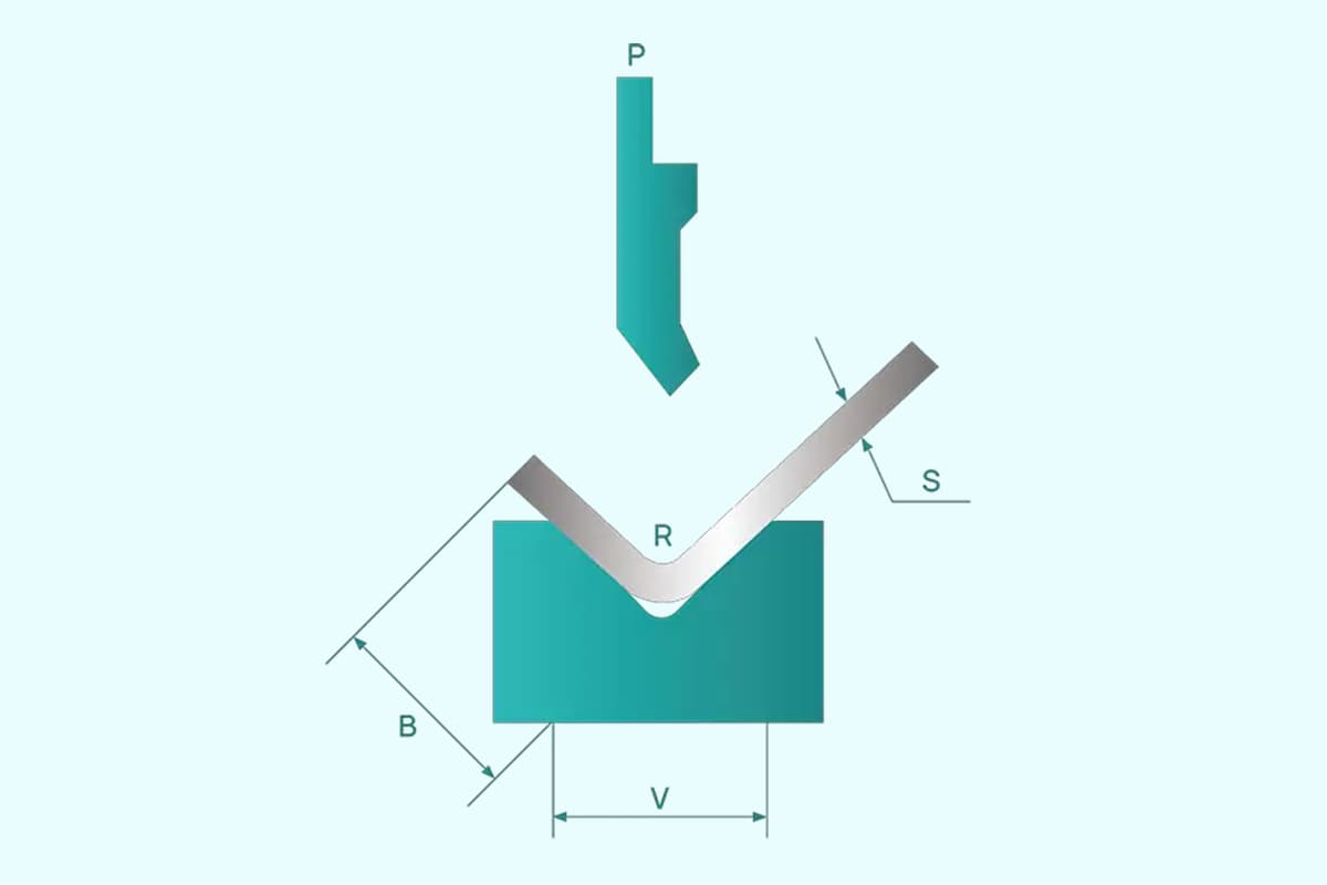
Ever wondered how to calculate the bending limits of sheet metal accurately? This article explores the essential formulas and guidelines for determining the minimum and maximum bending dimensions, ensuring precision in your metalworking projects. By understanding these calculations, you can optimize your designs and avoid costly errors. Dive into the specifics of flange sizes, Z-shaped hems, and U-shaped bends, and gain valuable insights that will enhance your sheet metal fabrication skills.
Lmin =(V/2)+ 2 + t ………(7)
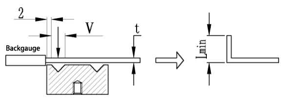
The minimum flange size, “lmin“, for various material thicknesses is listed in Table 5.
Table 5 minimum hem size Lmin
| Lmin | Material thickness t | ||||||||
| 1.0 | 1.2 | 1.5 | 2.0 | 2.5 | 3.0 | 4.0 | 5.0 | ||
| Width of lower mold groove | 8 | 7 | 7.2 | 7.5 | |||||
| 12 | 9.5 | 10 | |||||||
| 16 | 12.5 | 13 | |||||||
| 25 | 17.5 | 18.5 | 19.5 | ||||||
The height of the center of a Z-shaped flange is influenced by the distance from the center of the V-shaped groove to the bottom edge of the die.
The minimum flanging height is formula (8):
Hmin =(V/2)+ 2.5+ 2t ………(8)
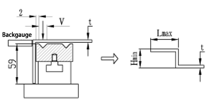
Refer to Table 6 for the minimum middle height, “Hmin“, of a Z-shaped hem for various material thicknesses.
Table 6 Minimum Z-shaped hem middle height Hmin
| Hmin | Material thickness t | ||||||||
| 1.0 | 1.2 | 1.5 | 2.0 | 2.5 | 3.0 | 4.0 | 5.0 | ||
| Width of lower die groove V | 8 | 8.5 | 8.9 | 9.5 | |||||
| 12 | 11.5 | 12.5 | |||||||
| 16 | 15.5 | 16.5 | |||||||
| 25 | 21 | 23 | 25 | ||||||
3.1 The maximum reverse side size of Z-shaped folding (as shown in Fig. 6).
The left door of the general switch cabinet features a Z-shaped fold, and its size on the reverse side is influenced by the height of the lower mold and the mold base.
The maximum reverse side height is formula (9):
Lmax = 59 + t …………(9)
3.2 When the center height of the Z-fold is less than 30, Table 7 displays the maximum reverse side size of the Z-fold for various material thicknesses.
When the center height of the Z-fold is significant, it may be impacted by various components of the lower die base of the bending machine. In such cases, the maximum size of the reverse side should be determined on site.
Table 7maximum reverse side size of Z-type hem
| Material thickness t | 1.0 | 1.2 | 1.5 | 2.0 | 2.5 | 3.0 | 4.0 | 5.0 |
| Lmax | 60 | 60.2 | 60.5 | 61 | 61.5 | 62 | 63 | 64 |
4.1 As depicted in Fig. 7, the width (H1) of the U-shaped hem should not be excessively narrow, and the height (H2) should not be overly large due to the impact of the machine tools and molds.
When the height (H2) reaches the minimum hem size specified in Table 5, the minimum value for the width (H1) can be calculated using formula (10).
H1 = 12 + 2t …………………(10)
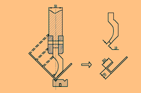
41.1 the value of H1 is shown in Table 8
| Material thickness t | 1.0 | 1.2 | 1.5 | 2.0 | 2.5 | 3.0 |
| H1 min | 14 | 15 | 15 | 16 | 17 | 18 |
4.1.2 When H1 value is large, it should meet: H2 < H1- 35.
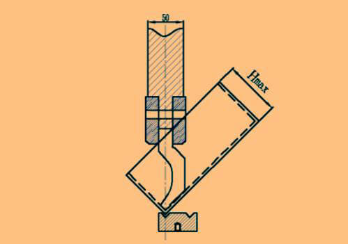
4.2 Maximum height of four side folding H
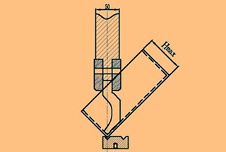
The maximum height of the four-side fold (Hmax) is limited to less than 175 due to the influence of the mold, as shown in Fig. 8.
