How do you transform raw copper and aluminum into critical components for electrical systems? This article delves into the intricate processes behind busbar fabrication, detailing the techniques and tools necessary for efficient assembly. You’ll learn about the precise methods of cutting, bending, and joining busbars, ensuring safety and reliability in high and low voltage applications. Explore the essential guidelines and best practices to enhance your understanding and implementation of busbar fabrication.

This document specifies the methods and requirements for busbar fabrication and assembly.
This document is applicable to the fabrication and assembly of busbars for high and low voltage switchgear, high/low voltage prefabricated substations, distribution boxes, and other complete equipment.

GB/T 17467-1998 High/Low Voltage Prefabricated Substations
GB/T 11022-1999 Common Technical Requirements for High Voltage Switchgear and Control Equipment
GB 7251.1~4 Low Voltage Complete Switchgear and Control Equipment
GBJ149-90 Electrical Installation Engineering
Specifications for Construction and Acceptance of Busbar Devices
Copper Busbar” International Copper Association (China)
Electric Power Industry Association Compilation of Electrical Regulations in Beijing Area
GB 5585.1-2005 Busbars for Electrical Purposes Part 1: General Provisions
GB 5585.2-2005 Busbars for Electrical Purposes Part 2: Copper Busbars
GB2681-81 Wire colors in Electrical Complete Devices
Copper busbars (rectangular, I-shaped, D-shaped, double T-shaped, triple T-shaped, etc.), aluminum busbars, insulators, heat shrinkable tubes, galvanized bolts, nuts, flat washers, spring washers, electrical contact conductive grease, (yellow, green, red), (L1, L2, L3) and various phase labels.
Busbar straightening machine, busbar cutting machine, busbar bending machine, polishing machine, punching machine, vertical drilling machine, electric furnace, tin pot, handsaw, file, screwdriver, hand hammer, wooden hammer, tape measure, steel rule, square, scribing needle, wire brush wheel, scissors, spray gun, wrench, torque wrench, etc.
5.1 The specification of the busbar is selected according to the technical requirements of the blueprint.
The routing scheme of the busbar is generally determined by the fabricator, but it should consider the installation position of the components and the actual installation conditions.
On the premise of meeting relevant technical requirements, it should adhere to the principles of reasonable layout, material saving, neatness, and aesthetics.
The installation should be safe, reliable, and easy to maintain and disassemble. The wiring of the same contract product should be as uniform as possible.
5.2 This document requires that the primary circuit generally use copper bars. In special cases, with the consent of the head of the technical department or the chief engineer, insulated wires can also be used. For continuous currents above 100A, copper bars should be used.
5.3 The specification of the primary line is determined according to the user’s blueprint requirements, but it should not be lower than this regulation. When the blueprint does not specify the specification, the corresponding specification should be found according to the wire capacity. See the “Wire Current Carrying Capacity Table” in this process guideline.
a) For the selection of TMY copper busbar current carrying capacity, see Appendix A.
b) For the current carrying capacity of BVR, BV PVC insulated wire, see Appendix B.
5.4 On the premise of meeting the above requirements, the number of busbar bends should be minimized to avoid busbar crossing.
6.1 The processing of the busbar generally includes the following technological processes:
a) Select the busbar specification according to the technical requirements of the blueprint, determine the wiring scheme, and measure the busbar manufacturing dimensions;
b) Straighten the copper busbar with a busbar straightening machine;
c) Cut according to the unfolded dimensions, the cross-section should be flat without burrs;
d) Drill or punch holes, deburr the marked holes;
e) Bend flat, vertical, and twist bends according to the plan; (The busbar surface should be clean and flat, without cracks, wrinkles, impurities, and deformations and twists.)
f) Do anti-oxidation treatment on the busbar overlap surface (tin or silver plating).
6.2 After the busbar is cut, it should be straightened, and the cut surface should be smoothed with a file.
6.3 The burrs after drilling or punching the busbar must be machined flat, and the busbar surface should not have obvious hammer marks, scratches, pits, peeling, and other defects.
6.4 Between the double busbars or multiple rectangular busbars, a gap not less than the thickness of the busbar should be maintained; the distance between the edges of adjacent spacers should be more than 5mm.
6.5 The same layout of the main busbar, branch busbar, drop line, and equipment connection line should be symmetrical, horizontal and vertical, neat and beautiful.
6.6 The phase sequence arrangement of the busbar, when the design does not specify, should comply with the following regulations:
a) For AC busbars arranged up and down, the arrangement from top to bottom is A, B, C, N phase, DC busbar positive pole is up, negative pole is down.
b) For horizontally arranged AC busbars, the arrangement from the back of the pan to the pan surface is A, B, C, N phase, DC busbar positive pole is at the back, negative pole is at the front.
c) For the AC busbar of the drop wire from left to right, the arrangement is A, B, C, N phase, DC busbar positive pole is on the left, negative pole is on the right.
Note: The phase sequence arrangement is based on the front view direction of each room of the substation. In special cases, when arranging in this phase sequence will definitely cause difficulties in busbar positioning, it is not necessary to follow this regulation, but each phase should have a clear indication.
6.7 Bending of Busbars
6.7.1 Rectangular busbars should be cold bent, hot bending is not allowed.
6.7.2 The bending of busbars should comply with the following regulations (Figure below):
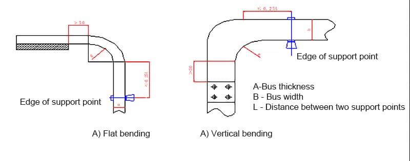
a) Rectangular busbars should minimize right-angle bends, and the bending angle must not be less than 90 degrees. There should be no cracks or significant wrinkles at the bend, and the minimum bending radius of the busbar should comply with the regulations, see figure below.

b) The distance from the point where the busbar begins to bend to the edge of the busbar support clamp of the nearest insulator should not exceed 0.25L, but must not be less than 50mm.
c) The distance from the point where the busbar begins to bend to the busbar connection location should not be less than 50mm.
Table 6.7.2: Minimum Bending Radius (r) Value for Busbars
| Busbar Type | Types of Bends | Busbar Cross-Sectional Size (mm) | Minimum Bending Radius (mm) | ||
| Copper | Aluminum | Steel | |||
| Rectangular Busbar | Flat Bend | 50×5 and below | 2a | 2a | 2a |
| 125×10 and below | 2a | 2.5a | 2a | ||
| Vertical Bend | 50×5 and below | 1b | 1.5b | 0.5b | |
| 125×10 and below | 1.5b | 2b | 1b | ||
| Rod-shaped Busbar | Φ16 and below | 50mm | 70mm | 50mm | |
| Φ30 and below | 100mm | 150mm | 150mm | ||
Note: ‘a’ is the thickness of the busbar and ‘b’ is the width of the busbar.
d) When the busbar is rotated 90°, the length of the rotated part should be 2.5 to 5 times the width of the busbar (Figure 6.7.2.2).
e) The bending of multiple busbars should be consistent.
6.8 Connections for rectangular busbars should be made using welding, bolts, or clamps. Cylindrical busbars should be connected using welding or wire clamps. The busbar connections should meet the following requirements:
6.8.1 When rectangular busbars are overlapped with bolt fixing, the distance from the connection to the edge of the insulator support plate should not be less than 50mm. The distance from the upper busbar end to the place where the lower busbar begins to bend should not be less than 50mm (Figure 6.8.1). (Note: If conditions permit, the two busbars can be directly overlapped without bending, but it must be ensured that the busbars are not subjected to external stress.)
6.8.2 Overlapping methods for rectangular busbars: When the busbars are connected to the equipment terminals, they should meet the requirements of the national standard “Connection terminals for transformers, high-voltage appliances, and bushings”. If necessary, dual or multiple busbar transition connections should be used. When there are no special requirements, they should comply with the regulations in the following table:
| Vertical Overlap | Serial Number | Connection Dimensions (mm) | Hole Diameter Φ | Bolt Specification | ||
| b2 | b1 | a | ||||
 | 1 | 15 | <2 b2 | 7 | M6 | |
| 2 | 20 | 11 | M10 | |||
| 3 | 25 | 11 | M10 | |||
| 4 | 30 | 13 | M12 | |||
 | 5 | 15 | ≥2b2 and ≤3b2 | 7 | M6 | |
| 6 | 20 | 11 | M10 | |||
| 7 | 25 | 11 | M10 | |||
| 8 | 30 | 13 | M16 | |||
 | 9 | 15 | ≥3b2 | 40 | 7 | M6 |
| 10 | 20 | 40 | 11 | M10 | ||
| 11 | 25 | 50 | 11 | M10 | ||
| 12 | 30 | 60 | 13 | M16 | ||
 | 13 | 40 | ≥40 | 11 | M10 | |
| 14 | 50 | ≥50 | 13 | M12 | ||
 | 15 | 60 | ≥60 | 11 | M10 | |
| 16 | 80 | ≥80 | 17 | M16 | ||
| 17 | 100 | ≥100 | 17 | M16 | ||
| 18 | 120 | ≥120 | 17 | M16 | ||
 | 1 | 15 | 15 | 30 | 7 | M6 |
| 2 | 20 | 20 | 40 | 11 | M10 | |
| 3 | 25 | 25 | 50 | 11 | M10 | |
| 4 | 30 | 30 | 60 | 13 | M12 | |
 | 5 | 40 | 40 | 80 | 11 | M10 |
| 6 | 50 | 50 | 80 | 13 | M12 | |
 | 7 | 60 | 60 | 60 | 11 | M10 |
| 8 | 80 | 80 | 80 | 17 | M16 | |
| 9 | 100 | 100 | 100 | 17 | M16 | |
| 10 | 120 | 120 | 120 | 17 | M16 | |

6.8.3 The diameter of the busbar joint screw hole should be larger than the bolt diameter by 1mm; drilling should be vertical, not skewed, and the error in the center distance between screw holes should be ±0.5mm.
6.8.4 The contact surface of the busbar must be flat and free of oxide films (polished with a wire brush wheel). After processing, the reduction in its cross-section: the copper busbar should not exceed 3% of the original cross-section; the aluminum busbar should not exceed 5% of the original cross-section.
6.8.5 For busbar overlap surfaces with a silver plating layer, arbitrary filing is not allowed. For silver-plated contact surfaces without blackening, simply wipe with anhydrous alcohol or acetone or gasoline until it plays out. If the silver layer turns black, you can lightly polish it with metallographic sandpaper, then wipe it with anhydrous alcohol.
6.8.6 The installation of the busbar and busbar or busbar and electrical terminal bolt overlap surfaces should meet the following requirements:
a) The busbar contact surface must be kept clean after processing.
b) When the busbar is placed flat, the through bolt should be threaded from bottom to top, in other cases, the nut should be on the maintenance side, and the bolt length should protrude from the nut by 2 to 5 threads.
c) There should be flat washers on both outsides of the busbar connected by the through bolt, there should be more than 3mm of net distance between adjacent bolt washers, and there should be a spring washer or lock nut on the nut side.
d) The bolts should be evenly stressed and should not subject the electrical terminal to extra stress.
e) The contact surface of the busbar should be tightly connected, the connecting bolts should be tightened with a torque wrench, and the tightening torque value should comply with the provisions of Table 6.8.6:
Table 6.8.6 Tightening Torque Value of Steel Bolts
| Bolt Specification (mm) | Torque Value (N·m) |
| M8 | 8.8~10.8 |
| M10 | 17.7~22.6 |
| M12 | 31.4~39.2 |
| M14 | 51.0~60.8 |
| M16 | 78.5~98.1 |
| M18 | 98.0~127.4 |
| M20 | 156.9~196.2 |
| M24 | 274.6~343.2 |
f) When the busbar is connected to the screw-shaped terminal, the aperture of the busbar should not exceed the diameter of the screw-shaped terminal by 1mm. The oxide film of the thread must be brushed clean. The contact surface of the nut must be flat. A copper tin-plated flat washer should be added between the nut and the busbar, and a lock nut should be provided, but no spring washer should be added.
g) After the busbar is installed, there should be no internal stress, and there should be no significant sag. The deviation within two support points should not exceed 4mm. All contact parts of the busbar joints should be closely combined. After the bolts are tightened, a 0.05mm feeler gauge should be used for inspection. The depth of the feeler gauge should not exceed 6mm for busbars with a width of over 60mm, and should not exceed 4mm for busbars with a width of less than 60mm.
6.8.7 The busbar should meet the following requirements when fixed on the pillar insulator:
6.8.7.1 The fixing of the busbar fitting and the pillar insulator should be flat and firm, and should not subject the supported busbar to extra stress. When the length of the busbar exceeds the provisions of Table 6.8.7.1, a fixed support should be added in the middle.
Table 6.8.7.1 Intervals for adding fixed support to busbars (mm).
| Busbar Width | Distance | Busbar Width | Distance | Busbar Width | Distance |
| ≤30 | 300 | ≤50 | 600 | ≥60 | 900 |
6.8.7.2 The fixing fittings or other support fittings of the AC busbar should not form a closed magnetic circuit.
6.8.7.3 When the busbar is laid flat, the upper pressure plate of the busbar support clamp should maintain a gap of 1mm ~ 1.5mm with the busbar. When the busbar is erected, the upper pressure plate should maintain a gap of 1.5mm ~ 2mm with the busbar.
6.8.7.4 For each section of the busbar fixed on the pillar insulator, a dead point should be set, preferably at the midpoint of the full length or between the two busbar expansion joints.
6.8.7.5 Every part of the busbar fixing device with edges and corners should be blunted to prevent tip discharge.
6.9 Selection of the cross-section of the neutral line N
6.9.1 In a three-phase four-wire power supply system, the cross-section of the N neutral line should be the same as that of the phase line.
6.9.2 The cross-sectional area of the PEN conductor should be determined in the same way as the neutral conductor N. However, the minimum cross-sectional area should not be less than 10 mm2. The cross-section of the protective conductor is selected according to Table 6.9.2.
Table 6.9.2 Reference table for the selection of the cross-sectional area of the protective conductor (mm2).
| Cross-sectional area S of the device phase conductor. | Minimum Cross-Sectional Area of Protective Conductor Sp |
| S≤16 | S |
| 16<S≤35 | 16 |
| 35<S≤400 | S / 2 |
| 400<S≤800 | 200 |
| S>800 | S/4 |
6.10 After the busbar is made, it should be insulated and protected by a heat shrink tube. The specific requirements are as follows:
6.10.1 Cutting: Select a heat shrink tube that matches the cross-section of the busbar. Cut the tube so that its length suits the busbar length, and there should be no oblique mouth. There should be no joints in the middle. (The tube length shrinks about 3% to 5%)
6.10.2 Insertion: Insert the busbar. If insertion is difficult, you can spray lubricants such as silicone oil on the busbar to prevent creases and facilitate insertion.
6.10.3 Start Shrinking: Use medium heat to shrink. For Z-shaped busbars, start shrinking from the middle of the busbar. At the same time, keep the flame moving to prevent the tube from being scorched.
6.10.4 Shrinking of the Right Angle Part: When the right angle part shrinks, tighten the tube to prevent creases caused by small fire.
6.10.5 Shrinking of the Second Right Angle Part: Similarly, tighten the tube and keep the flame moving.
6.10.6 Shrinking of the Straight Part: Keep the flame moving and use medium heat for even heating.
6.10.7 Bubble Issue: If bubbles appear on the tube, thoroughly heat it with medium heat until the bubbles disappear.
6.10.8 Correction: If there are wrinkles or overstretching on the surface of the tube, correct it before cooling to fit the busbar.
6.10.9 Cooling: Cool the busbar to complete the shrinking process.
6.10.10 After heat shrinking, the busbar should be checked for flatness, scorching, rupture, and scratches, and it should be neatly coded.
6.11 The overlap surface of the busbar and the heat shrink position of the heat shrink tube are shown in the figure:

6.12 Rectangular busbars should avoid the arc area. When the main AC circuit passes through a metal frame forming a closed magnetic circuit, the three-phase busbars should pass through the same frame hole. When connecting the secondary line on the primary busbar, it is necessary to drill holes separately on the busbar and fasten it with bolts.
6.13 The insulating wires in the device are generally black unless the user has special requirements. The grounding wire is yellow and green. The wire ends are distinguished by different colors of insulated ends or different colored plastic sleeves. Copper and aluminum busbars are labeled with color labels for phase sequence identification.
a. AC circuit: Phase A – Yellow, Phase B – Green, Phase C – Red, Neutral – Light Blue, Ground – Yellow and Green.
b. DC circuit: Positive – Brown, Negative – Blue.
6.14 The busbar overlap should not be spray-painted; adhesive color labels can be used at conspicuous positions on the busbar observation surface.
6.15 The color and phase sequence of the busbars are shown in Appendix C.
6.16 The requirements for busbar insulation clearance should meet the following requirements:
6.16.1 The electrical gap on the low-voltage side should not be less than 20mm.
6.16.2 The gap between the bare live bodies of different phases on the high-voltage side and between the bare live parts and the grounded skeleton should not be less than 125mm; the gap between the bare live parts and the front metal cover plate, metal door, or transmission rod should not be less than 155mm; the gap between the bare live parts and the front net cover plate or net door should not be less than 225mm.
6.16.3 After the busbar is installed, it should comply with the design regulations, the connections should be correct, the bolts should be fastened, the contact should be reliable, the phase color marking should be conspicuous, not easy to fall off, and the end should be neat and attractive.
Note: The above dimensions cannot be used as the basis for electrical insulation strength. The electrical gap of the electrical components themselves is not subject to the above size restrictions.
7.1 Pay attention to personal safety during the production of busbars to prevent bumps, scratches, and burns;
7.2 The manufactured busbar should not be climbed, stepped on, or pulled;
7.3 The busbar material used should be neatly stacked to prevent getting dirty and deformation;
7.4 Pay attention to the hygiene of the work site.
2904-1 General technical rules for wiring auxiliary circuits
2905-1 Technical rules for the processing and fixing of marking and symbol plates.
Appendix A
(Suggestive Appendix)
TMY Busbar Current Carrying Capacity Table
| Rated Current (A) | Copper Busbar Specifications (Single Piece in mm) |
| Below 185 | 16×1.6、15×3、10×4 |
| 242 | 20×3 |
| 300 | 25×3、16×5 |
| 355 | 30×3、20×4 |
| 420 | 30×4、20×6 |
| 550 | 40×4、30×5、20×10 |
| 615 | 50×3、40×5、30×6、25×8 |
| 755 | 60×3、50×5、40×6、30×10 |
| 840 | 60×4、50×6、40×8、25×16 |
| 900 | 80×3、60×5 |
| 990 | 60×6、50×8、40×10、30×16 |
| 1160 | 80×4、60×8、50×10、40×16 |
| 1300 | 100×4、80×6、60×10、50×12 |
| 1490 | 100×5、80×8、60×12、50×16 |
| 1590 | 100×6 |
| 1670 | 80×10、60×16 |
| 1830 | 120×6、100×8、80×12 |
| 2030 | 100×10 |
| 2110 | 120×8、100×12、80×16 |
| 2330 | 160×6、120×10、100×16 |
| Rated Current (A) | Copper Busbar Specifications (Double Piece in mm) |
| 1530 | 60×6 |
| 2300 | 80×8 |
| 2730 | 80×10 |
| 2690 | 100×8 |
| 3180 | 100×10 |
| 3610 | 120×10 |
Note: Ambient temperature is 35°C, and the maximum working temperature is 70°C.
Appendix B
(Informative Appendix)
Current Carrying Capacity of BVR, BV PVC Insulated Copper Core Wires
| Wire Cross-Section (mm2) | Wire Laying (A) |
| 1 | 6 |
| 1.5 | 8 |
| 2.5 | 12 |
| 4 | 16 |
| 4 | 25 |
| 6 | 32 |
| 10 | 40 |
| 10 | 63 |
| 16 | 80 |
| 25 | 100 |
| 35 | 125 |
| 50 | 160 |
| 70 | 200 |
| 95 | 250 |
| 120 | 300 |
| 150 | 315 |
| 185 | 400 |
Note: The current carrying capacity is the empirical current value when the ambient temperature is 35℃ and the wire is exposed. Select according to technical requirements in special cases.
Appendix C
(Suggestive Appendix)
Busbar Color and Phase Sequence (Installation location is according to the front view of the screen/cabinet)
| Group | Busbar Installation Positions Relative to Each Other | ||||
| Color | Horizontal Arrangement | Front and Back Arrangement | Vertical Arrangement. | ||
| Alternating Current | Phase A | Yellow | Left | Far | Top |
| Phase B | Green | Middle | Medium | Middle | |
| Phase C | Red | Right | Near | Bottom | |
| Neutral Line | Light Blue | Further Right | Closer | Further Bottom | |
| PE Line | Yellow-Green Alternating | Farthest Right | Closest | Lowest | |
| Direct Current | Positive | Brown | Left | Far | Top |
| Negative | Blue | Right | Near | Bottom | |
| Neutral Line | Light Blue | – | – | – | |

