Standard CAD Drawing Frame Size: Unlocking the Secrets
Have you ever wondered why precise standards matter in technical drawings? Understanding the correct CAD drawing frame size is crucial for ensuring consistency and clarity in engineering designs. This article outlines the standard sizes for drawing frames, including details on title blocks and binding edges. By the end, you’ll know exactly how to format your CAD drawings to meet industry standards, ensuring your designs communicate effectively.
Like illustrations and text, technical drawings serve as one of the primary tools for humans to express design concepts, facilitate technical communication, and organize construction and production.
They act as the “common language” in the engineering field. As with any “common language,” there are shared standards, and drawing frames also adhere to a set of such standards.
According to the current drafting standard GB/T14689-93, various standard paper sizes for drawings are outlined.
These should be prioritized when creating engineering drawings. If necessary, the length of the sides can be extended, but the extent of the extension must comply with the standard regulations.
Below are the standard sizes for A4 to A0 drawing frames.
Drawing Sheet Code
A0
A1
A2
A3
A4
BXL
841X1189
594X841
420X594
297X420
210X297
a
25
c
10
5
e
20
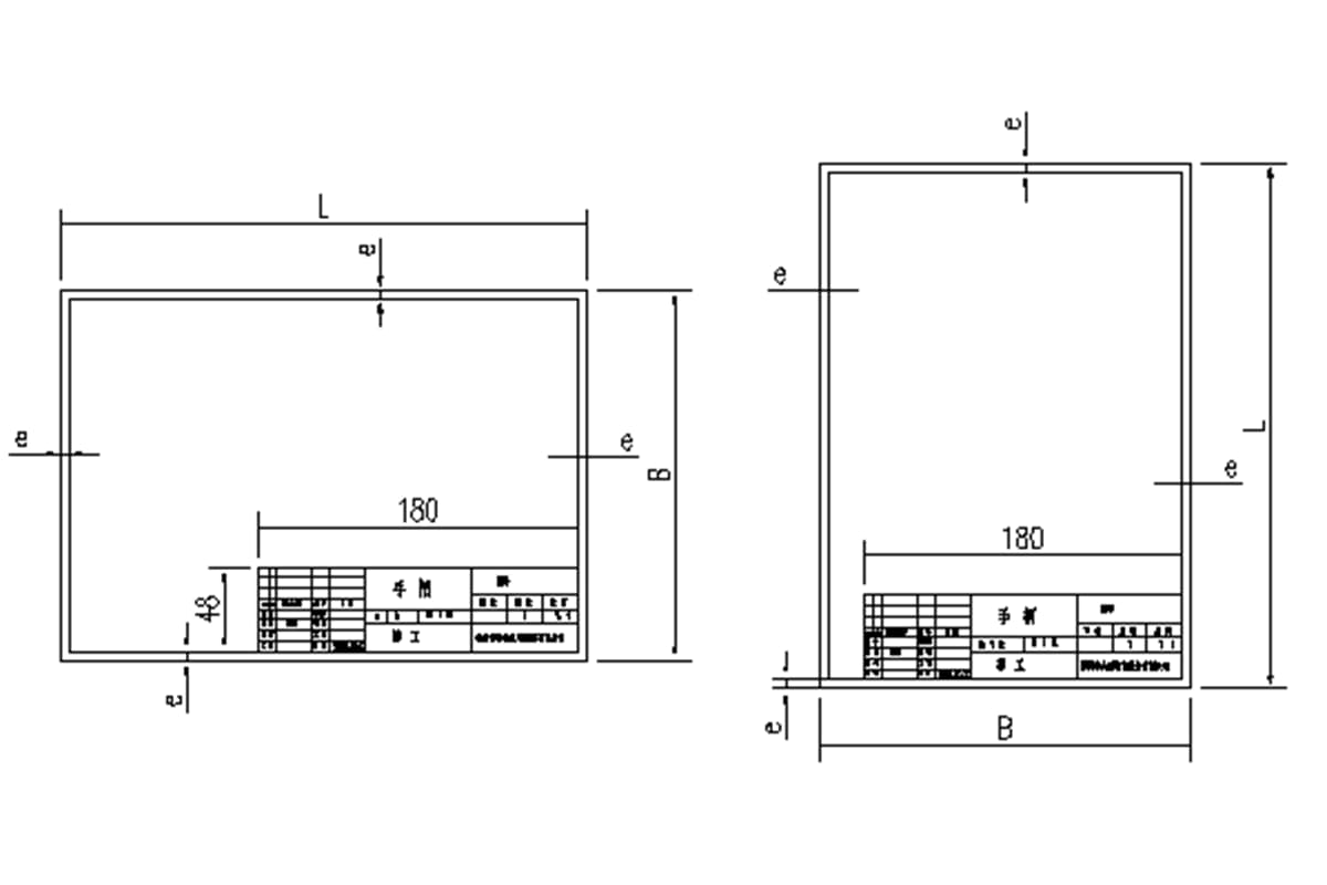
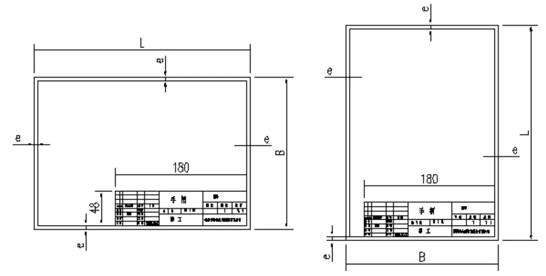
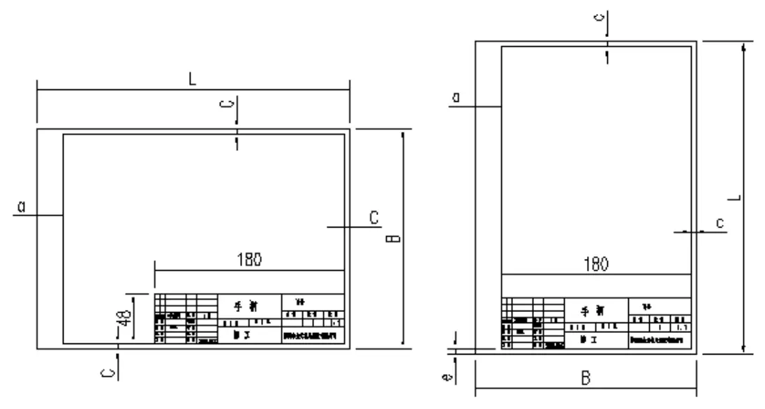
Each drawing frame consists of a thickly drawn frame and title bar. If the drawing needs to be bound, a binding edge should be reserved.
For drawings that don’t require binding, there’s no need for a binding edge. The dimensions of the borders around the drawing can be uniform. (See the image below.)
Standard Drawing Frame Without Binding
Standard Drawing Frame with Binding
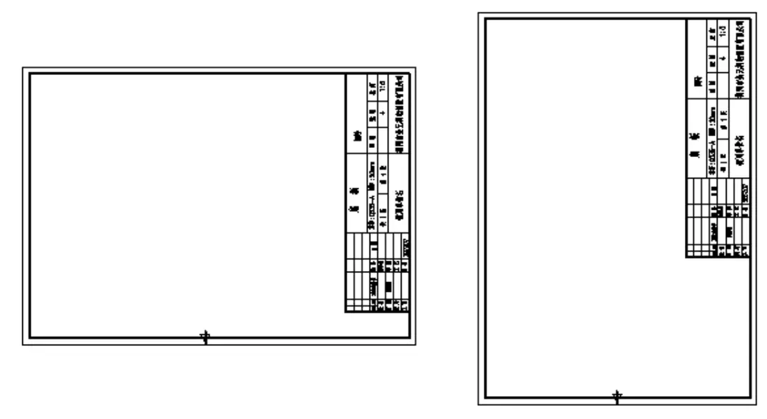
Title Block Orientation:
The title block can be placed in any corner of the drawing frame, but it’s typically located in the lower right corner, as shown above.
However, there can be exceptions, where it might be positioned in the upper right corner or along the right side. It is recommended to include a directional icon. (See the image below.)
As the founder of MachineMFG, I have dedicated over a decade of my career to the metalworking industry. My extensive experience has allowed me to become an expert in the fields of sheet metal fabrication, machining, mechanical engineering, and machine tools for metals. I am constantly thinking, reading, and writing about these subjects, constantly striving to stay at the forefront of my field. Let my knowledge and expertise be an asset to your business.
Have you ever wondered which bearing brands are the best in the world? In this blog post, we'll explore the top bearing manufacturers known for their exceptional quality, innovation, and…
Have you ever wondered who powers the world behind the scenes? In this blog post, we'll take a deep dive into the top generator manufacturers that keep the lights on…
Are you an aspiring mechanical engineer looking to excel in your field? In this blog post, we'll explore the top 10 must-know mechanical engineering design software that can elevate your…
Have you ever wondered how the gears in your car or airplane work so smoothly? This article unveils the top gear manufacturers shaping the future of mechanical engineering. You'll learn…
Ever wondered how the world of automation thrives? This article explores top pneumatic companies driving innovation. From Japan to Germany, discover how these industry leaders shape our future. Expect insights…
Have you ever wondered who powers the machines that keep our world running? In this blog post, we'll introduce you to the top compressor manufacturers that are driving innovation and…
Have you ever wondered what keeps our gas systems running smoothly and safely? In this article, we explore top gas regulator manufacturers, uncovering their innovations and contributions to the industry.…
Are you aware of the pivotal players in the centrifugal pump industry? This article dives into the leading manufacturers revolutionizing the market with innovative and reliable pumping solutions. From Bosch…
Have you ever wondered how the industrial world keeps running smoothly? Compressed air is the unsung hero behind countless manufacturing processes. In this blog post, we'll explore the fascinating world…