Ever wondered how to determine the perfect steel beam for your project? This article will guide you through the essentials of calculating the load-bearing capacity of H-beams and I-beams. By the end, you’ll know how to choose the right beam and ensure your structure’s safety and efficiency.
Understanding the load capacity of steel beams, particularly H-beams, is crucial for ensuring structural integrity and safety in construction projects. This section will guide you through the process of calculating beam load capacity and selecting the appropriate H-beam size for your specific requirements.
Load Capacity Calculation and Beam Selection:
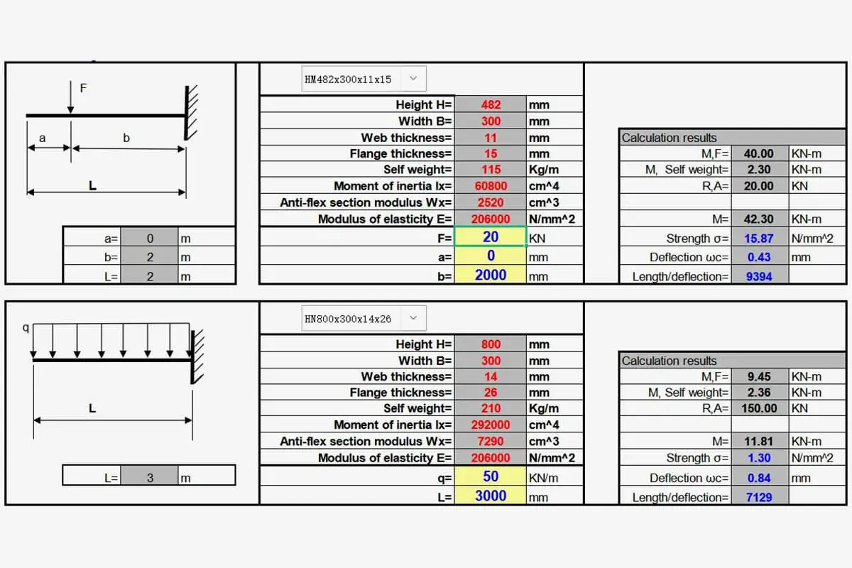
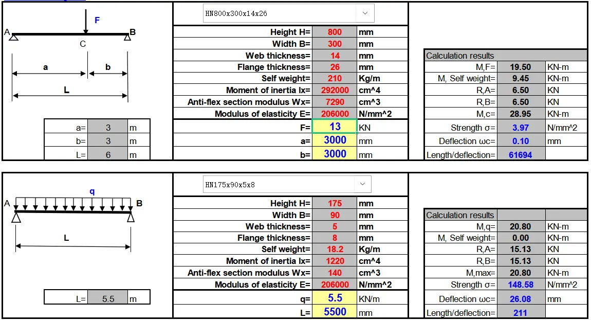
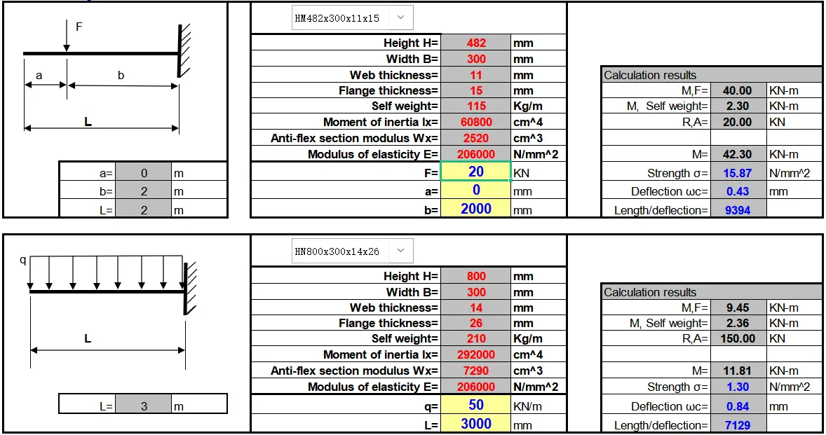
To determine the weight capacity of a steel H-beam or to select the proper size for your construction project, you can utilize our comprehensive beam load capacity calculator and reference the accompanying load capacity chart. These tools, as illustrated in the screenshot below, provide a robust and user-friendly method for making informed decisions about beam selection.
Beam Size and Geometry: The dimensions of the H-beam, including flange width, web thickness, and overall depth, significantly impact its load-bearing capacity.
Material Properties: The grade of steel used in the H-beam affects its strength and, consequently, its load capacity.
Span Length: The distance between supports directly influences the beam’s ability to carry loads.
Load Distribution: Whether the load is uniformly distributed or concentrated at specific points affects the beam’s performance.
Safety Factors: Engineers typically incorporate safety factors to account for unexpected loads or material variations.
F – design value of yield strength b – web thickness b ‘- flange width h – high h ‘- flange thickness
As for the bearing capacity of tension and compression, I think it is not necessary for me to explain here. As for eccentric tension and compression, it is not very difficult to calculate by yourself.
For example:
How much can I-beam #25 bear when the span is 4m and the load is evenly distributed?
Calculation:
For #25 I-beam, W = 401.4cm3, [σ]=210N/mm2, overall stability coefficient φb=0.93
Bending moment formula M = QL2/8 Strength formula σ = M/W
According to the formula: q=8σW/L2=8*210*401400/4*4=42.1kN/m
The above calculation does not consider the self-weight and deflection checking calculation of I-beam.
Which of H-Beam Steel and I-Beam Steel Bears Better Load?
H-beam steel demonstrates superior load-bearing capabilities compared to I-beam steel, owing to its optimized structural design and enhanced mechanical properties.
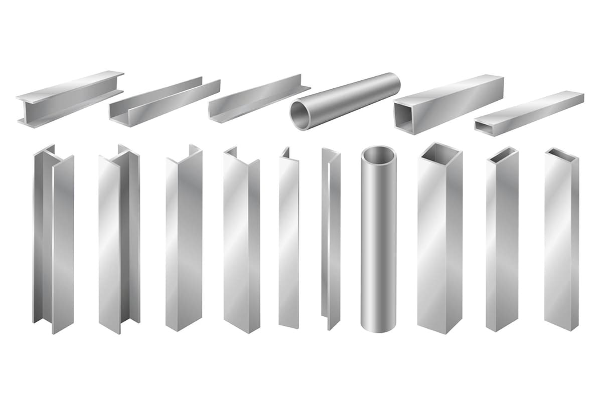
The cross-sectional geometry of I-beam steel, characterized by its relatively high and narrow profile, results in significant disparities between the moments of inertia along its two principal axes. This asymmetry limits its application primarily to scenarios involving bending loads within the plane of its web or as components in lattice stress-bearing structures. I-beams are less suitable for axial compression or bending perpendicular to the web plane, which constrains their versatility in structural applications.
In contrast, H-beam steel presents a more efficient and economical profile due to its well-engineered cross-sectional shape. The key advantages of H-beams include:
Improved Section Modulus: The wider flanges and optimized web thickness result in a higher section modulus, enhancing the beam’s resistance to bending moments.
Enhanced Moment of Inertia: The geometry of H-beams provides a more balanced distribution of material, leading to improved moments of inertia about both principal axes.
Superior Connectivity: The parallel or near-parallel inner and outer flange surfaces facilitate easier connections with other structural elements, particularly when using high-strength bolts.
Comprehensive Size Range: H-beams offer a well-designed series of sizes and models, streamlining the design and selection process for engineers.
Increased Load Capacity: When subjected to bending moments, pressure loads, or eccentric loads, H-beams exhibit superior performance compared to ordinary I-beams of equivalent weight.
Material Efficiency: The optimized design of H-beams can result in material savings of 10% to 40% compared to standard I-beams in similar applications.
Balanced Strength: The wider flanges and optimized web thickness provide more uniform strength characteristics in multiple directions, enhancing overall structural stability.
The parallel flange design of H-beams, also known as wide flange I-beams, contributes to their improved performance. This configuration results in a more efficient distribution of material, leading to enhanced section properties and increased resistance to various loading conditions.
In summary, while both H-beam and I-beam steel have their places in structural engineering, H-beam steel generally offers superior load-bearing capabilities, greater versatility, and improved material efficiency. These characteristics make H-beams the preferred choice for many load-bearing applications in modern structural design and construction.
As the founder of MachineMFG, I have dedicated over a decade of my career to the metalworking industry. My extensive experience has allowed me to become an expert in the fields of sheet metal fabrication, machining, mechanical engineering, and machine tools for metals. I am constantly thinking, reading, and writing about these subjects, constantly striving to stay at the forefront of my field. Let my knowledge and expertise be an asset to your business.
Have you ever wondered how to accurately calculate the weight of steel or metal for your projects? In this blog post, we'll explore the fascinating world of steel weight calculation…
Curious about the weight of your steel project? Look no further! In this blog post, we'll explore the intriguing world of steel weight calculation. As a seasoned mechanical engineer, I'll…
Have you ever wondered about the fascinating world of metal densities? In this blog post, we'll dive into the importance of understanding metal densities for mechanical engineers. As an experienced…
Have you ever struggled to calculate the exact weight of stainless steel for a project? Understanding the varying densities of different stainless steel grades is crucial. This article provides a…
Why do different types of steel have such varied properties, and how are they categorized in China? This article breaks down the classification and standards of steel, explaining the systematic…
Have you ever considered how critical precise measurements are in steel production? In the world of steel, dimensions such as length, width, diameter, and thickness aren't just numbers—they ensure the…
Have you ever wondered how the strength of stainless steel is measured so precisely? This article explores the fascinating world of stainless steel hardness testing. You'll learn about the different…
Have you ever wondered how the carbon content in metals is precisely measured? This article explores various methods, from infrared absorption to electrochemical analysis, shedding light on their principles and…
Have you ever wondered about the difference between the standard and actual thickness of stainless steel? In this blog post, we'll dive into this intriguing topic, exploring the key factors…