L Bending
1) Factors determining the minimum L bending
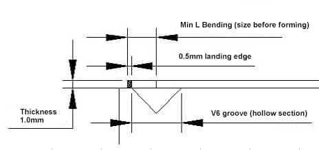
As the middle of the press brake V groove is hollow, when forming, the edge fold must be longer than the hollow section and the specific landing edge size varies in the production of different companies (the lower section of V groove is under use for a long time, the R angle increases, which makes the scrap edge distance increases accordingly, otherwise, “sliding” will happen)
2) Reduction formula (empirical): 6T/2+0.5+(1.8T/2)
3) As the picture below shows, when T=1, K=1.8*1, the minimum L Bending is 3+0.5+0.9=4.4
| V Groove/Thickness | 3 | 4 | 5 | 6 | 7 | 8 | 9 | 10 | 12 | 15 | 16 | 18 |
| 0.5 | 2.5 | 3 | ||||||||||
| 0.8 | 3.2 | 3.7 | 4.2 | |||||||||
| 1 | 3.5 | 4 | 4.5 | 5 | 5.5 | |||||||
| 1.2 | 3.5 | 4 | 4.5 | 5 | 5.5 | |||||||
| 1.5 | 4.8 | 5.2 | 5.8 | 6.2 | 6.8 | |||||||
| 2 | 7.5 | 8.5 | ||||||||||
| 3 | 11 | 12 | ||||||||||
| 4 | 15 | 16 | ||||||||||
| 5 | ||||||||||||
| 19 | 20 | |||||||||||
| 22 | 24 | 26 | 28 | 30 |
U Bending
1) U bending types
A. Regular forming by press brake punch
B. Gasket-reverse folding-hemming (firstly bending to 30°, placing a suitable gasket in the middle and then hemming )
2) Factors determining the minimum U bending
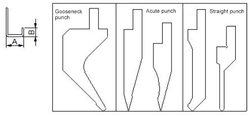
- Shapes of punch (shown in the following picture).
Judging from common punch mold, the best one for U folding is “gooseneck punch” which has many types and specifically subject to the requirement of various companies.
- Bending size (shown in the following picture).
The increasing relation between two sizes:
The longer A is, the longer B is.
3)Reduction formula (empirical value of gooseneck punch )
◆ 0.5MM sheet:
Minimum U bending: A =7.67, B= 0.5, minimum L bending=3.0
Increasing value: whenever A increases by 1mm, B increases 1.87 accordingly.
Formula: when A size is known, then B size=(A-7.67)/T*increasing value + the minimum L bending value of this plate
For example,
when A=15, then B=(15-7.67)/0.5*1.87+3.0=30.4
When B size is known, then A size=(B- the minimum L bending value of this plate)/increasing value *T+7.67
For example,
when B=30.4, then A=(30.4-3)/1.87*0.5+7.67=15
◆ 0.8MM sheet
Min U bending A size=8.5,B size=0.8, min L bending=4.2。
Increasing value:1.87/0.5*0.8=2.99
◆ 1.0MM sheet
Min U bending A size=8.94, B size =1.0, min L bending=4.5
Increasing value: 1.87/0.5*1.0=3.7
◆ 1.2MM sheet
Min U bending A size=9.3, B=1.2, min L bending=4.5
Increasing value: 1.87/0.5*1.2=4.5
◆ 1.5MM sheet
Min U bending A size=10.3, B= 1.5, min L bending=6.2
Increasing value: 1.87/0.5*1.5=5.5
◆ 2.0MM sheet
Min U bending A size=12.7, B= 2.0, min L bending=12.0
Increasing value: 1.87/0.5*2=7.4
Notes:
- When A size exceeds 85.0MM and B size exceeds 60.0MM, this formula is inapplicable.
- Attached table: A= test value, B= minimum L bending, K=test value
| Thickness | A size (min) | B size (min) | K |
|---|---|---|---|
| 0.5 | 7.67 | 3 | 1.87 |
| 0.8 | 8.5 | 4.2 | 2.99 |
| 1 | 8.94 | 4.5 | 3.7 |
| 1.2 | 9.3 | 4.5 | 4.5 |
| 1.5 | 10.3 | 6.2 | 5.5 |
| 2 | 12.7 | 12 | 7.4 |
Related: V & U-shaped Bend Force Calculator
Z Bending
1) Z Bending Types
- When H is larger than or equal to 5T, calculating as per two 90°bending.
- When H is lower than 5T, one-time forming is enough
2) The main factors that affect the minimum Z bending value are the width of V groove and the distance from the center of the V groove to the edge.
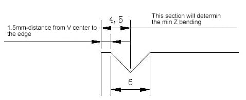
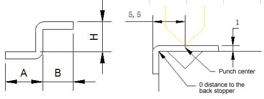
3) Formula: 6T/2+edge distance of V groove +(1.8T/2)+T(see the picture)
For example, in the case of 1.0mm plate, to the edge distance=1.5, then the minimum Z bending H=61/2+1.5+(1.81/2)+1=6.4.
Calculation of minimum bending edge of one bend
The starting state of the L-bend is shown in the following illustration:
Reference table for bending inner R and minimum bending height of the cold-rolled sheet
| No. | Thickness | Die Groove Width | Convex die R | Min Bending Height |
| 1 | 0.5 | 4 | 0.2 | 3 |
| 2 | 0.6 | 4 | 0.2 | 3.2 |
| 3 | 0.8 | 5 | 0.8/0.2 | 3.7 |
| 4 | 1.0 | 6 | 1/0.2 | 4.4 |
| 5 | 1.2 | 8/6 | 1/0.2 | 5.5/4.5 |
| 6 | 1.5 | 10/8 | 1/0.2 | 6.8/5.8 |
| 7 | 2.0 | 12 | 1.5/0.5 | 8.3 |
| 8 | 2.5 | 16/14 | 1.5/0.5 | 10.7/9.7 |
| 9 | 3.0 | 18 | 2/0.5 | 12.1 |
| 10 | 3.5 | 20 | 2 | 13.5 |
| 11 | 4.0 | 25 | 3 | 16.5 |
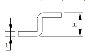
The starting state of the Z-bend is shown in the following illustration:
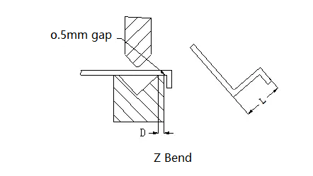
The minimum bending size (L) of the sheet metal corresponding to Z-bend for materials with different thickness is shown in the following table:
| No. | Thickness | Die Groove Width | Convex die R | Z Bending Height |
| 1 | 0.5 | 4 | 0.2 | 8.5 |
| 2 | 0.6 | 4 | 0.2 | 8.8 |
| 3 | 0.8 | 5 | 0.8/0.2 | 9.5 |
| 4 | 1.0 | 6 | 1/0.2 | 10.4 |
| 5 | 1.2 | 8/6 | 1/0.2 | 11.7/10.7 |
| 6 | 1.5 | 10/8 | 1/0.2 | 13.3/12.3 |
| 7 | 2.0 | 12 | 1.5/0.5 | 14.3 |
| 8 | 2.5 | 16/14 | 1.5/0.5 | 18.2/17.2 |
| 9 | 3.0 | 18 | 2/0.5 | 20.1 |
| 10 | 3.5 | 20 | 2 | 22 |
| 11 | 4.0 | 25 | 3 | 25.5 |