Ever wondered how to ensure top-notch quality in laser cutting? This article outlines nine essential standards for evaluating the precision and effectiveness of laser cuts. You’ll learn to assess factors like roughness, perpendicularity, cutting width, and more. By understanding these criteria, you’ll be able to judge and improve the performance of your laser cutting machine, leading to better results and efficiency in your metalworking projects. Discover the key metrics that define superior laser cutting quality.
The quality of a laser cutting machine is mainly determined by its cutting quality, which is the most direct way to assess the machine. When purchasing a laser cutting machine, new customers typically request to see a sample cutting process performed by the machine.
See also:
The cutting speed of the laser cutting equipment is important for customers to consider. Additionally, they should also focus on the cutting quality of the sample.
So, how do you assess the quality of laser cutting, and what should you pay attention to? Let me provide you with some more details.
The following nine standards are important to keep in mind.
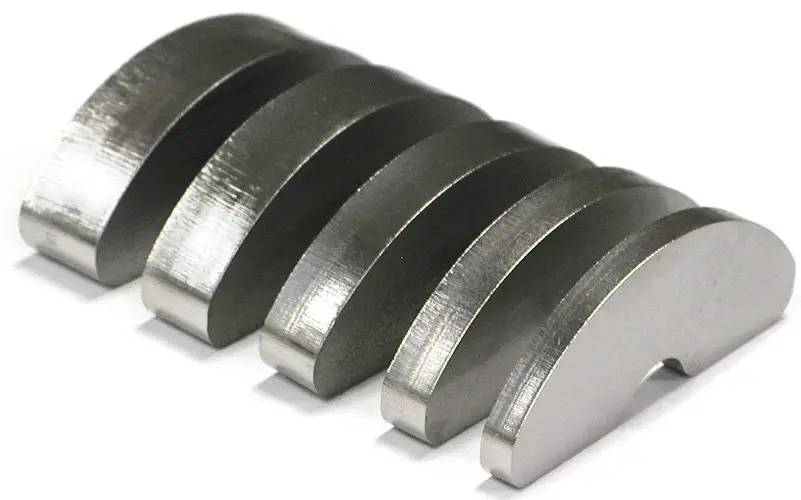
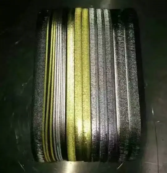
Laser cutting produces characteristic vertical striations on the cut edge, with the depth and frequency of these striations determining the surface roughness. The intensity and pattern of these lines are directly correlated to the cutting quality and surface finish.
Lighter, less pronounced striations indicate a smoother cutting surface, resulting in lower roughness values (Ra). This smoother finish is generally desirable for most applications, as it enhances both aesthetic appeal and functional performance.
Surface roughness significantly impacts not only the visual appearance of the cut edge but also its tribological properties, including friction characteristics, wear resistance, and potential for material adhesion. A smoother surface typically exhibits lower friction coefficients and improved wear resistance, which can be crucial for parts subject to dynamic contact or requiring precise fits.
In the majority of laser cutting applications, minimizing surface roughness is a primary objective to achieve optimal part quality. Consequently, lighter, more uniform striations are indicative of superior cutting quality. Factors influencing the formation of these striations include laser power, cutting speed, assist gas pressure, and material properties.
To quantify and control roughness, manufacturers often employ surface roughness measurements (e.g., Ra, Rz values) and may specify acceptable ranges based on the application requirements. Advanced laser cutting systems can optimize parameters in real-time to maintain consistent surface quality across varying material thicknesses and compositions.
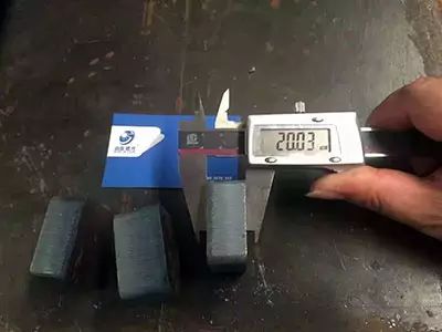
When sheet metal thickness exceeds 10mm, the perpendicularity of the cutting edge becomes critical for both dimensional accuracy and subsequent processing operations. The laser beam’s inherent divergence as it propagates from its focal point significantly impacts the cut quality in thick materials.
As the beam travels through the material, it diverges, causing the kerf (cutting width) to vary. This divergence can result in a tapered cut, where the width at the top or bottom of the cut is wider, depending on the focal position relative to the material surface. For instance, if the focus is set at the top surface, the kerf will typically widen towards the bottom of the cut.
The deviation from true perpendicularity can range from a fraction of a millimeter to several millimeters, depending on material thickness and laser parameters. This deviation is quantified as the perpendicularity or squareness tolerance, often expressed as a percentage of material thickness or an absolute value.
Achieving high perpendicularity is crucial for several reasons:
To optimize perpendicularity in thick-section cutting:
By carefully controlling these parameters, it’s possible to achieve cutting edge perpendicularity within ±0.05mm for many thick-section applications, significantly enhancing overall part quality and reducing the need for post-processing.
The kerf width, commonly referred to as cutting width, plays a crucial role in laser cutting precision and part quality. While it generally does not significantly impact overall cutting quality, it becomes a critical factor when fabricating parts with high-precision outlines or intricate features.
The kerf width directly influences the minimum internal diameter achievable in outlined shapes. As plate thickness increases, the cutting width typically expands due to the laser beam’s divergence and increased material interaction time. This relationship between material thickness and kerf width must be carefully considered in precision applications.
To maintain consistent high precision across varying material thicknesses and cutting widths, several factors should be optimized:
See also:

When cutting thick plates at high speeds, the molten metal generated by the laser beam doesn’t accumulate in the kerf below the vertical beam. Instead, it’s ejected from the bottom of the cut, trailing the laser’s movement. This phenomenon occurs due to the high-pressure assist gas and the momentum of the rapidly moving molten metal.
As a result, characteristic curved striations form on the cut edge, following the trajectory of the advancing laser beam. These striations, often referred to as drag lines, can affect the cut quality and dimensional accuracy of the workpiece.
To mitigate this issue, implementing a dynamic feed rate control strategy is crucial. Specifically, reducing the feed rate towards the end of the cutting process can significantly minimize the formation of these curved lines. This deceleration allows for better melt evacuation and reduces the lag between the top and bottom of the cut, resulting in straighter, more parallel striations and improved edge quality.
For optimal results, consider the following techniques:
Burr formation is a critical factor that significantly impacts the quality and efficiency of laser cutting operations. These undesirable protrusions of material along the cut edge not only affect the dimensional accuracy and surface finish of the workpiece but also necessitate additional post-processing steps, potentially increasing production time and costs.
The severity and extent of burr formation are paramount considerations in assessing cutting quality. Burrs are typically classified based on their size, shape, and location:
Several factors influence burr formation during laser cutting:
Minimizing burr formation is crucial for achieving high-quality cuts and reducing post-processing requirements. This can be accomplished through:
Prior to initiating the perforation process, the laser cutting system applies a specialized anti-spatter coating to the workpiece surface. This thin, oily film serves as a protective barrier against molten material adhesion.
During the cutting operation, the high-energy laser beam vaporizes the workpiece material, generating a mixture of gaseous and particulate matter. To maintain cut quality and prevent contamination, a high-pressure assist gas (typically nitrogen or oxygen, depending on the material) is directed coaxially with the laser beam. This gas jet serves dual purposes: it expels molten material from the kerf and provides oxidation or inert shielding.
However, the forceful ejection of vaporized and molten material can lead to unwanted deposition on the workpiece surface. This deposition may occur in both the upward direction (on the top surface) and the downward direction (on the bottom surface), potentially affecting surface finish and dimensional accuracy. The pattern and extent of deposition depend on factors such as material properties, cutting parameters, and assist gas flow dynamics.
To mitigate these effects, optimized cutting parameters, proper gas flow control, and post-process cleaning techniques may be necessary to achieve the desired surface quality and precision in laser-cut components.
Surface depressions and corrosion can significantly impact the quality and integrity of the cutting edge, compromising both the functional performance and aesthetic appearance of the workpiece.
Depressions, often resulting from uneven pressure distribution or tool wear, can create localized stress concentrations and dimensional inaccuracies. These imperfections may lead to premature fatigue failure or improper component fit in assemblies. Corrosion, whether chemical or galvanic, deteriorates the material surface, reducing its strength and potentially initiating crack propagation.
To mitigate these issues, several preventive measures can be implemented:
In laser cutting, the area adjacent to the cut undergoes significant thermal effects, resulting in microstructural changes within the metal. This thermally affected region is known as the Heat Affected Zone (HAZ).
The intense, localized heat from the laser beam causes rapid heating and cooling cycles, which can induce various metallurgical transformations. For instance, in steels, this thermal cycling can lead to the formation of martensite, a hard and brittle phase, effectively hardening the material near the cut edge. Conversely, in some aluminum alloys, the heat can cause localized softening due to the dissolution of strengthening precipitates.
The extent of the HAZ, often measured in micrometers, depends on several factors including laser power, cutting speed, material properties, and thickness. Minimizing the HAZ is crucial for maintaining the mechanical properties and dimensional accuracy of the cut part. Advanced laser cutting systems employ precise control of laser parameters and assist gases to optimize cut quality while minimizing thermal effects.
Understanding and managing the thermal zone is essential for achieving high-quality cuts and ensuring the structural integrity of laser-cut components, particularly in applications requiring tight tolerances or specific material properties.

Rapid localized heating during laser cutting can induce thermal stresses, potentially leading to part deformation. This phenomenon is particularly critical in precision manufacturing, where intricate features and thin connecting sections may be only a few millimeters wide. The thermal gradient created by the laser beam can cause differential expansion and contraction, resulting in warping, bending, or distortion of the workpiece.
To mitigate these thermal effects and maintain dimensional accuracy, several strategies can be employed:

