Ever wondered how the tiniest gap in a machine can make or break its performance? This article dives into bearing clearance, the small but crucial space that affects a machine’s lifespan, temperature, noise, and vibration. Learn how understanding radial and axial clearance can optimize your machinery’s efficiency and durability.
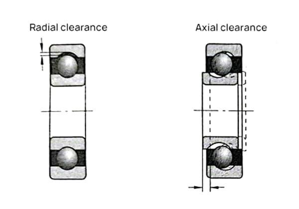
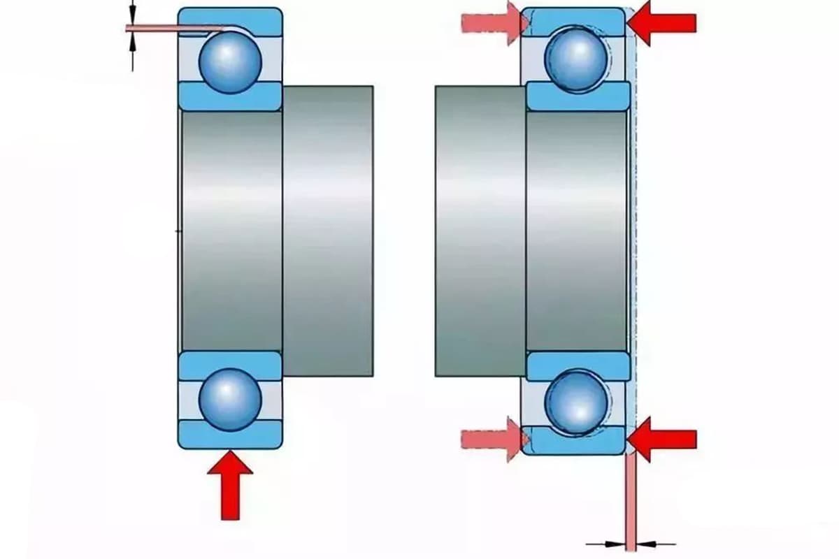
Bearing clearance, also known as bearing play, refers to the radial or axial movement of a bearing before it is installed on a shaft or into a bearing housing. One ring of the bearing is fixed, and the bearing can move towards the side that isn’t secured.
This movement is typically classified into radial clearance and axial clearance. The operational clearance of a bearing during its use significantly influences its lifespan, temperature rise, noise, and vibration characteristics.
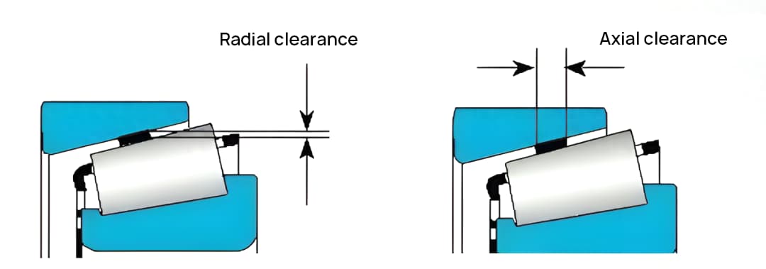
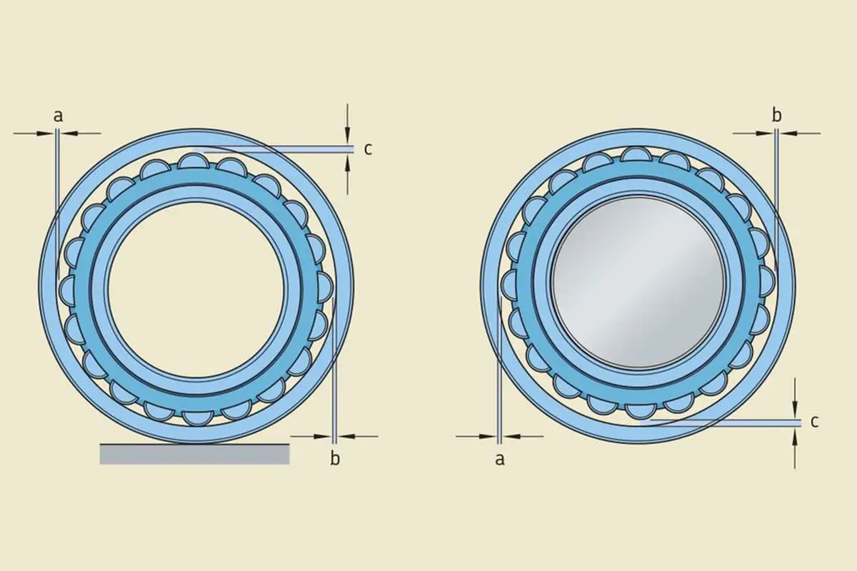
When a bearing that sustains radial load is not preloaded, its radial clearance G is defined as the average radial distance produced when the outer ring, under no external load conditions, moves from one side’s eccentric limit position to the opposite extreme position.
For a bearing capable of withstanding bidirectional axial load and not preloaded, its internal axial clearance G is defined as the average axial distance produced when one ring, under no external load conditions, moves from one side’s axial limit position to the opposite extreme position.
Permissible tolerance for shaft neck roundness
| Newly machined shaft | Unprocessed old shaft | ||||
| Bearing diameter (mm) | High speed above 1000rpm | Low speed below 1000rpm | Bearing diameter (mm) | High speed above 1000rpm | Low speed below 1000rpm |
| 50~70 | 0.01 | 0.03 | 50~70 | 0.03 | 0.05 |
| 70~150 | 0.02 | 0.04 | 70~150 | 0.04 | 0.06 |
Maximum allowable wear value for rolling bearings
| Bearing Diameter (mm) | Radial Clearance (mm) | Axial Clearance (mm) |
| Under 30 | 4D/1000 | 0.2 |
| 35 to 70 | 3.5D/1000 | 0.3 |
| 75 to 100 | 3D/1000 | 0.3 |
| Above 100 | Not exceeding 0.3 | 0.3 |
Note: D – Bearing inner diameter or shaft neck diameter
Standard for original radial clearance of new bearings
| Nominal Diameter of Bearing (mm) | Single-Row Spherical Roller Bearing (Threads) | Single-Row Short Cylindrical Roller Bearing (Threads) | Double-Row Spherical Roller Bearing (Threads) | Apply radial load (in MPa) during measurement. | The allowable wear value after use is (in threads). | ||||
| Exceeding | To | Minimum | Maximum | Minimum | Maximum | Minimum | Maximum | ||
| 18 | 24 | 1.0 | 2.4 | 0.5 | 10 | ||||
| 24 | 30 | 1.0 | 2.4 | 0.5 | |||||
| 30 | 40 | 1.2 | 2.6 | 1.0 | 20 | ||||
| 40 | 50 | 1.2 | 2.9 | 2.0 | 5.5 | 1.0 | |||
| 50 | 65 | 1.3 | 3.3 | 2.5 | 6.5 | 1.0 | 20 | ||
| 65 | 80 | 1.4 | 3.4 | 3.0 | 7.0 | 5.0 | 8.0 | 1.0 | |
| 80 | 100 | 1.6 | 4.0 | 3.5 | 8.0 | 6.0 | 10.0 | 1.0 | |
| 100 | 120 | 2.0 | 4.6 | 4.0 | 9.0 | 1.5 | |||
| 120 | 140 | 2.3 | 5.3 | 4.5 | 10.0 | 1.5 | 30 | ||
The maximum movement of one ring of a rolling bearing fixed, and the other ring able to move in the radial or axial direction is the clearance of the rolling bearing. In most cases, the larger the bearing radial clearance, the larger the axial clearance.
According to the state of the bearing, the clearance can be divided into: original clearance, installation clearance, and working clearance.
Installation clearance directly affects the normal operation of the rolling bearings.
Too small clearance may lead to a higher temperature rise of the rolling bearings, or even cause the rolling body to get stuck; if the clearance is too large, it may cause significant vibration in the equipment and generate a lot of noise.
Original clearance:
It is the clearance when the bearing is in a free state before installation, generally determined during processing and assembly.
Installation clearance:
Also known as matching clearance, it’s the clearance when the bearing is assembled with the shaft or bearing seat, but has not yet started working. The installation clearance is usually smaller than the original clearance, mainly because the inner ring of the bearing expands or the outer ring reduces after installation.
Working clearance:
This is the clearance when the bearing is in operation. During operation, the bearing will reduce the clearance due to the temperature rise and thermal expansion of the inner ring, and increase the clearance due to the elastic deformation of the contact position of the rolling body and the raceway under load.
Reference standards for motor bearing assembly
| Bearing Type | Bearing Inner Diameter and Shaft Fit Method with Tolerance | |||||
| Nominal Bearing Inner Diameter (mm) | Allowable Bearing Inner Diameter Tolerance (millimeters) | Allowable Shaft Tolerance (millimeters) | Fit Method | Interference Value of Shaft Neck and Bearing Inner Ring Fit (Difference Between Shaft Diameter and Actual Bearing Inner Diameter) (millimeters) | ||
| Exceeding | To | |||||
| Single-row radial ball bearing | <18 | 0-1.00 | 0.2 | gb | +1~+2 | |
| 18 | 30 | 0-1.00 | 0.2 | gb | +1~+2 | |
| 30 | 50 | 0-1.20 | 1 | gb | +2~+3 | |
| 50 | 80 | 0-1.50 | 1.2 | gb | +2~+3 | |
| 80 | 120 | 0-2.00 | 1.3 | gb | +3~+5 | |
| 120 | 180 | 0-2.5 | +1.9(+2.8)+0.3(+1.2) | gb | +4~+7 | |
| Single-row cylindrical roller bearing | 30 | 50 | 0-1.20 | 2.9 | gb | +1~+3 |
| 50 | 80 | 0-1.50 | 3.4 | gb | +2~+4 | |
| 80 | 120 | 0-2.00 | +2.8(+3.5)+1.2(+1.2) | gb | +4~+6 | |
| 120 | 180 | 0-2.5 | 9.2 | gb | +4~+7 | |
| Double-row spherical roller bearing | gb | |||||
| Bearing Outer Diameter and Housing End Cap Fit Method with Tolerance | |||||
| Nominal Bearing Outer Diameter | Allowable Bearing Outer Diameter Tolerance (millimeters) | Allowable Housing End Cap Tolerance (millimeters) | Fit Method | Clearance Between Bearing Outer Ring and Housing End Cap Hole (millimeters) | |
| Exceeding | To | ||||
| 18 | 30 | 0-0.90 | 0.9 | Gd | 0~3 |
| 30 | 50 | 0-1.10 | 1 | Gd | 0~3 |
| 50 | 80 | 0-1.30 | 1 | Gd | 0~3 |
| 80 | 120 | 0-1.50 | 1.1 | Gd | 0~3 |
| 120 | 160 | 0-2.50 | 1.3 | Gd | 0~3 |
| 180 | 260 | 0-3.50 | 1.2 | Gd | 0~3 |
| 260 | 315 | 0-3.50 | 1.7 | Gd | 0~3 |
| 80 | 120 | 0-1.5 | 1.1 | Gd | 0~3 |
| 120 | 180 | 0-2.5 | 1.3 | Gd | 0~3 |
| 180 | 260 | 0-3.5 | 1.4 | Gd | 0~3 |
| 260 | 315 | 0-3.5 | 1.7 | Gd | 0~3 |
| 120 | 180 | 0-2.5 | +2.7(+2.7)-1.4(0) | Gd | 0~3 |
Selection of Radial Clearance:
The radial clearance of a bearing must be chosen based on the specific conditions; smaller is not necessarily better. The radial clearance of rolling bearings is divided into five groups. Group 0 is the standard base radial clearance group.
Bearings in Group 0 are commonly applied in general operating conditions, conventional temperatures, and frequently used interference fits. Bearings with larger radial clearances are suitable for special operating conditions such as high temperatures, high speeds, low noise, and low friction. Bearings with even larger radial clearances are suitable for precision spindle bearings and similar uses.
| Deep Groove Ball Bearing Axial Clearance | ||||||
| Ga=0.4w√ GrDw | (C3) | |||||
| Nominal Inner Diameter(d) | 0.4 | Gr | Dw | (Square Root) | Ga | Range |
| ≤30 | 0.4 | 8 | 3.5 | 0.08 | 0.032 | 0.02-0.05 |
| >30~50 | 0.4 | 27 | 4 | 0.1 | 0.04 | 0.03-0.06 |
| >50~80 | 0.4 | 38 | 5 | 0.14 | 0.056 | 0.05-0.08 |
| >80~100 | 0.4 | 51 | 7 | 0.19 | 0.076 | 0.07-0.10 |
| >100~120 | 0.4 | 61 | 8.5 | 0.23 | 0.092 | 0.09-0.12 |
| >120~140 | 0.4 | 68.5 | 9 | 0.25 | 0.1 | 0.10-0.14 |
Selection of Axial Clearance:
For deep groove ball bearings and tapered roller bearings, when they are mounted face-to-face or back-to-back, the internal clearance or preload typically requires the axial position of a sleeve to determine, and the bearing configuration performance and operation requirements should be considered.
The axial clearance and radial clearance of these types of bearings usually only need to satisfy one of these values.
The selection of radial clearance for rolling bearings is crucial as it is one of the critical factors that determine whether the bearings can function properly.
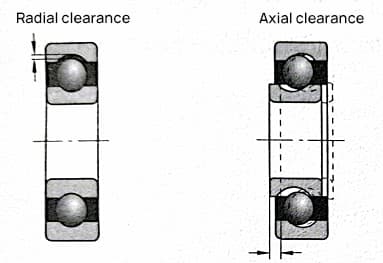
Proper selection of radial clearance can ensure the reasonable distribution of loads between the rolling elements of the bearing. It can limit the axial and radial displacement of the shaft (or housing), guarantee the rotational accuracy of the shaft, and enable the bearing to operate under given temperatures while reducing vibration and noise. This is advantageous in improving the service life of bearings.
The difference between the theoretical clearance and the clearance generated by the interference fit of the housing or the shaft with the bearing after expansion or shrinkage of the collar is installed is referred to as “installation clearance”.
Upon adding or subtracting the accumulated dimensional changes due to thermal variations inside the bearing, it is referred to as “operational clearance”.
The operational clearance refers to the existing clearance when the bearing is mounted on a machine and undergoes loading and rotation. The effective clearance plus the elastic deformation generated by bearing loads is known as the “operational clearance”.
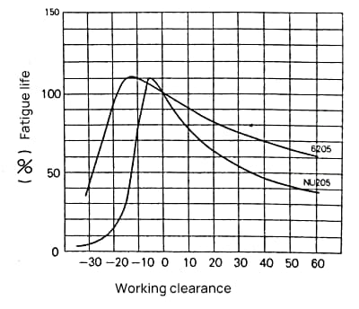
As shown in Figure 2, the bearing has the longest fatigue life when the operational clearance is marginally negative. However, as the negative clearance increases, the fatigue life of the bearing decreases notably.
Therefore, when selecting the clearance for bearings, it is generally suitable to have a slightly positive or zero value for operational clearance.
When selecting radial clearance for bearings, the following factors should be taken into consideration:
Based on experience, the optimal operational clearance for ball bearings is close to zero, while roller bearings should maintain a small amount of operational clearance.
In components that require good support rigidity, bearings can allow for a certain amount of preloading.
Under normal working conditions, it is recommended to choose the basic component first to achieve a suitable operational clearance for the bearing. If the basic component does not meet the requirements, then an auxiliary component should be chosen.
The large radial clearance auxiliary component is suitable for bearings with interference fit between the bearing and the shaft or housing. The small radial clearance auxiliary component is suitable for applications that require high rotational accuracy, strict control of the axial displacement of the housing, and noise and vibration reduction.
Furthermore, to improve the stiffness of the bearing or to reduce noise, the operational clearance should be further reduced, while to account for severe temperature increase of the bearing, the operational clearance should be further increased. Specific analysis should be conducted based on the usage conditions.

