Why does motor bearing clearance matter? The clearance impacts bearing performance, affecting everything from operational efficiency to lifespan. This article explains the importance of motor bearing clearance, types of clearances, and how to select the right one for your application. Learn about the factors that influence clearance, such as installation and temperature changes, and discover practical tips to ensure optimal bearing operation and longevity.
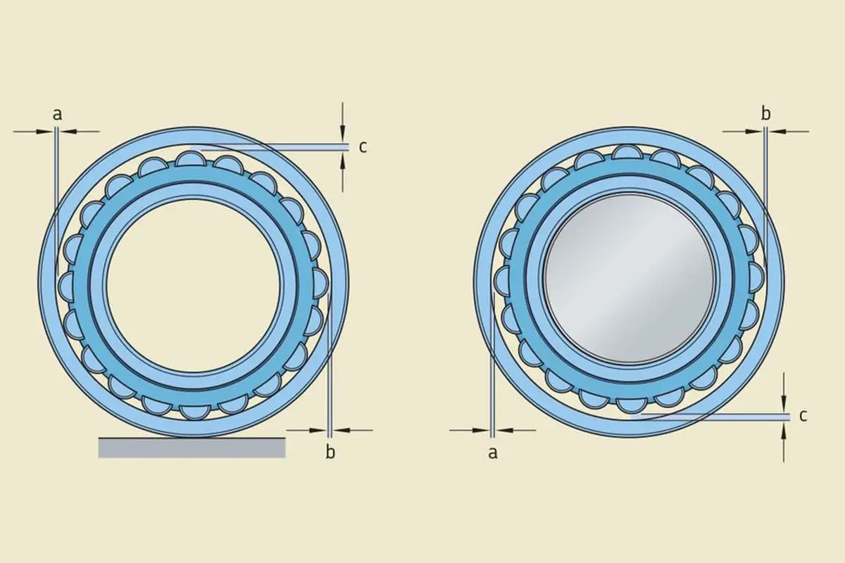
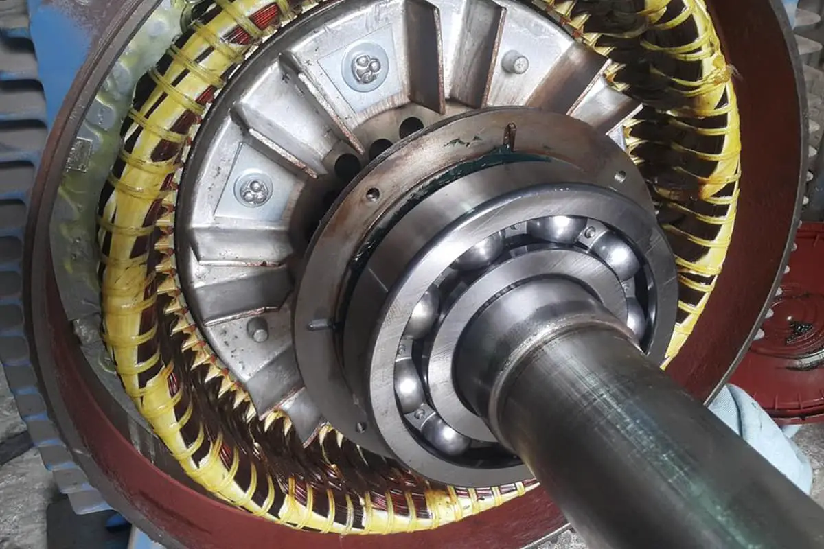
Generally, we consider the components of a bearing to include: the inner ring, outer ring, rolling element, cage, seals, and lubrication. Indeed, during past lectures to motor engineers, the clearance of a motor bearing has been listed as one of the components of a bearing.
Of course, clearance is an air gap, not a physical component, but the attention engineers pay to clearance in design, installation, use, and maintenance is no less than any physical part of the bearing.

Bearing clearance typically refers to the movement of one ring relative to a fixed ring on the bearing. If this movement is axial, it is called axial clearance; if it is radial, it is called radial clearance.
The following figure shows the radial and axial clearance of a deep groove ball bearing:
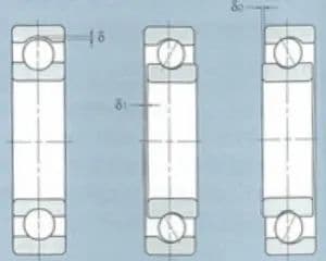
In the figure:
Clearances for bearings are governed by corresponding national and international standards. For example, the commonly used radial clearance for rolling bearings, GB/T4604-93, categorizes clearances as follows:
The standard also specifies other clearance groups. In practical applications, the clearances most often used for industrial motor bearings are from the standard clearance group (Group 0) and Group C3.
Table 1: Radial Clearance of Deep Groove Ball Bearings (Cylindrical Bore) – Unit: µm
| Nominal Inner Diameter of the Bearing | Clearance | ||||||||||
| d mm | C2 | Standard | C3 | C4 | C5 | ||||||
| Exceeding | To | Min | Max | Min | Max | Min | Max | Min | Max | Min | Max |
| 25 | 6 | 0 | 7 | 2 | 13 | 8 | 23 | – | – | – | – |
| 6 | 10 | 0 | 7 | 2 | 13 | 8 | 23 | 14 | 29 | 20 | 37 |
| 10 | 18 | 0 | 9 | 3 | 18 | 11 | 25 | 18 | 33 | 25 | 45 |
| 18 | 24 | 0 | 10 | 5 | 20 | 13 | 28 | 20 | 36 | 28 | 48 |
| 24 | 30 | 1 | 11 | 5 | 20 | 13 | 28 | 23 | 41 | 30 | 53 |
| 30 | 40 | 1 | 11 | 6 | 20 | 15 | 33 | 28 | 46 | 40 | 64 |
| 40 | 50 | 1 | 1 | 6 | 23 | 18 | 36 | 30 | 51 | 45 | 73 |
| 50 | 65 | 1 | 15 | 8 | 28 | 23 | 43 | 38 | 61 | 55 | 90 |
| 65 | 80 | 1 | 15 | 10 | 30 | 25 | 51 | 46 | 71 | 65 | 105 |
| 80 | 100 | 1 | 18 | 12 | 36 | 30 | 58 | 53 | 84 | 75 | 120 |
| 100 | 120 | 2 | 20 | 15 | 41 | 36 | 66 | 61 | 97 | 90 | 140 |
| 120 | 140 | 2 | 23 | 18 | 48 | 41 | 81 | 71 | 114 | 105 | 160 |
| 140 | 160 | 2 | 23 | 18 | 53 | 46 | 91 | 81 | 1130 | 120 | 180 |
| 160 | 180 | 2 | 25 | 20 | 61 | 53 | 102 | 91 | 147 | 135 | 200 |
| 10 | 200 | 2 | 30 | 25 | 71 | 63 | 117 | 107 | 163 | 150 | 230 |
| 200 | 225 | 2 | 35 | 25 | 85 | 75 | 140 | 125 | 195 | 175 | 265 |
| 225 | 250 | 2 | 40 | 30 | 95 | 85 | 160 | 145 | 225 | 205 | 300 |
| 250 | 280 | 2 | 45 | 35 | 105 | 90 | 170 | 155 | 245 | 225 | 340 |
| 280 | 315 | 2 | 55 | 40 | 115 | 100 | 190 | 175 | 270 | 245 | 370 |
| 315 | 355 | 3 | 60 | 45 | 125 | 110 | 210 | 195 | 300 | 275 | 410 |
| 355 | 400 | 3 | 70 | 55 | 145 | 130 | 240 | 225 | 340 | 315 | 460 |
Radial clearance of deep groove ball bearings
| (1) Round Housing Bore Tolerance – Unit in Micrometers (μm) | |||||||||||
| Nominal Inner Diameter of the Bearing | Clearance | ||||||||||
| d mm | C2 | Standard | C3 | C4 | C5 | ||||||
| Exceeding | To | Min | Max | Min | Max | Min | Max | Min | Max | Min | Max |
| – | 10 | 0 | 25 | 20 | 45 | 35 | 60 | 50 | 75 | – | – |
| 10 | 24 | 0 | 25 | 20 | 45 | 35 | 60 | 50 | 75 | 65 | 90 |
| 24 | 30 | 0 | 25 | 20 | 45 | 35 | 60 | 50 | 75 | 70 | 95 |
| 30 | 40 | 5 | 30 | 25 | 50 | 45 | 70 | 60 | 85 | 80 | 105 |
| 40 | 50 | 5 | 35 | 30 | 60 | 50 | 80 | 70 | 100 | 95 | 125 |
| 50 | 65 | 10 | 40 | 40 | 70 | 60 | 90 | 80 | 110 | 440 | 140 |
| 65 | 80 | 10 | 45 | 40 | 75 | 65 | 100 | 90 | 125 | 130 | 165 |
| 80 | 100 | 15 | 50 | 50 | 85 | 75 | 110 | 105 | 140 | 155 | 190 |
| 100 | 120 | 15 | 55 | 50 | 90 | 85 | 125 | 125 | 165 | 180 | 220 |
| 120 | 140 | 15 | 60 | 60 | 105 | 100 | 145 | 145 | 190. | 20 | 245 |
| 140 | 160 | 20 | 70 | 70 | 120 | 115 | 165 | 165 | 21.5 | 225 | 275 |
| 160 | 180 | 25 | 75 | 75 | 125 | 120 | 170 | 170 | 220 | 250 | 300 |
| 180 | 200 | 35 | 90 | 90 | 145 | 140 | 195 | 195 | 250 | 275 | 330 |
| 200 | 225 | 45 | 105 | 105 | 165 | 160 | 220 | 220 | 280 | 305 | 365 |
| 225 | 250 | 45 | 110 | 110 | 175 | 170 | 235 | 235 | 300 | 300 | 395 |
| 250 | 280 | 55 | 125 | 125 | 195 | 190 | 260 | 260 | 330 | 375 | 440 |
| 280 | 315 | 55 | 130 | 130 | 205 | 200 | 275 | 275 | 350 | 410 | 485 |
| 315 | 355 | 65 | 145 | 145 | 225 | 225 | 305 | 305 | 385 | 455 | 535 |
| 355 | 400 | 100 | 190 | 190 | 180 | 280 | 370 | 370 | 460 | 510 | 600 |
| 400 | 450 | 110 | 210 | 210 | 310 | 310 | 410 | 410 | 510 | 565 | 665 |
| 450 | 500 | 110 | 220 | 220 | 330 | 330 | 440 | 440 | 550 | 625 | 735 |
For motor engineers, the most commonly used bearing types are deep groove ball bearings and cylindrical roller bearings. If clearances for other types of bearings are required, they can be obtained from the relevant national standards or manufacturers.
Firstly, the bearing clearance values mentioned in the above standards are initial values, that is, the clearance values when the bearing has not been installed or used. When the bearing is installed, put into operation, and in a working state, the clearance value is a critical factor in bearing operation.
Generally, the fit between the rotor of the internal-rotation motor and the bearing is relatively tight, while the fit between the bearing housing and the outer ring of the bearing is relatively loose. In this way, the inner ring of the bearing will expand outward, which will reduce the clearance. We call this the reduction of installation clearance.
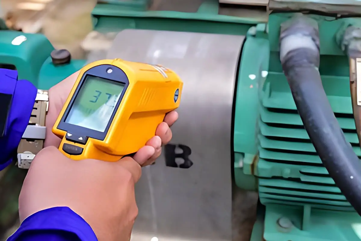
When the bearing is in the working state, there is usually a temperature difference between the inner and outer rings of the bearing, which leads to different degrees of thermal expansion of the inner and outer rings of the bearing, thus changing the clearance. We call this the reduction of clearance caused by temperature.
Therefore, the actual working clearance of the bearing is the initial clearance minus both the reduction of installation clearance and the reduction of clearance caused by temperature.
δwork = δinitial – δinstall – δtemperature
The lifespan of a typical motor bearing is related to its operational clearance as follows:

It’s clear to see that the highest lifespan of the bearing occurs when its clearance is a value less than zero. This implies that theoretically, when the operational clearance of the bearing is negative, the bearing’s life is at its longest.
However, operating at this clearance value carries a risk. By examining the slope of the curve on both sides, it becomes apparent that when the actual operational clearance is less than the clearance at maximum lifespan, the slope of the curve is steep, and with further decrease in clearance, the lifespan drops dramatically.
In contrast, an increase in clearance results in a much slower decrease in bearing life.
Therefore, if the bearing’s operational clearance is at the optimal value for maximum lifespan, any further reduction due to changes in operating conditions will rapidly decrease the bearing lifespan. This is what we commonly refer to as ‘bearing seizure’.
Considering all the above, in actual operating conditions, we often choose an operational clearance slightly greater than zero for the bearing. This is a safe value, ensuring the impact on bearing life, regardless of changes in operational clearance, remains within a controllable range.
Typically, motor engineers opt for clearances from the Normal or C3 group when selecting bearing clearances. (This is associated with the tolerance fit we commonly use and the internal temperature distribution in the motor.)
Naturally, if operating conditions are unique, the bearing clearance value would need to be verified through calculations to ensure the bearing operates under a safe clearance condition.

