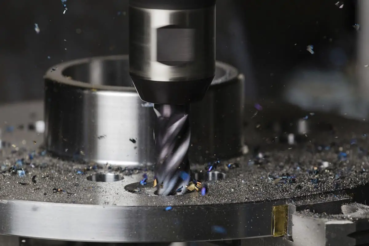
Choosing the Right Cutting Tools for CNC Milling in Mold Making
Imagine having the perfect tool for every unique challenge in mold making. From intricate free-form surfaces to high-precision requirements, selecting the right cutting tools for CNC milling can dramatically influence your efficiency and results. This article dives into the essential criteria for choosing these tools, ensuring optimal performance and quality in mold manufacturing. By understanding the nuances of different cutters and their applications, you’ll enhance your machining processes and achieve superior outcomes. Dive in to discover how to make the most informed choices for your CNC milling projects.
In the forming manufacturing of modern molds, as the aesthetics and functional requirements of new products in industries such as mechanical electronics, automobiles, and home appliances increase, increasingly complex components make the mold surface more intricate.
The proportion of free-form surfaces is continually increasing, which poses higher demands on mold processing technology. Due to the complex structure of the mold and high precision requirements, the surface features and materials of different parts vary significantly, necessitating the use of different types of mold milling cutters.
II. Selection of Machining Methods
1. The choice of tools for CNC milling in mold manufacturing greatly depends on the task at hand.
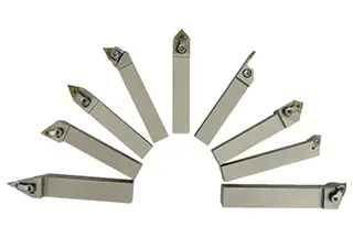
For milling the internal and external contours of parts and planar milling, flat-bottomed end mills are often used. For some three-dimensional surfaces and contours with changing angles, spherical mills, annular mills, drum-shaped mills, conical mills, and disc mills are commonly employed.
Mold milling cutters are used for machining mold cavity surfaces. The cavity section’s machining primarily relies on various types of end mills. Mold milling cutters have evolved from end mills and can be categorized by the shape of their working part into flat-tipped conical, spherical-tipped cylindrical, and spherical-tipped conical types.
They can also be classified by material into carbide mold milling cutters, high-speed steel mold milling cutters, etc. Carbide mold milling cutters have extremely broad applications. In addition to milling various mold cavities, they can replace hand files and grinding wheel heads for deburring cast, forged, and welded workpieces, and for fine finishing of certain shaped surfaces.
2. Mold Milling Cutter Selection.
The rational tool life generally falls into two categories: maximum production rate tool life and minimum cost tool life. The former is determined based on the objective of the least time per piece, while the latter is determined based on the objective of the lowest operation cost.
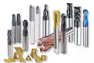
Compared to traditional machining methods, CNC machining imposes higher requirements on tools. Not only do they need to be rigid and precise, but they also need to have stable dimensions, high tool life, and easy installation and adjustment to meet the high efficiency requirements of CNC machine tools. The tools used on CNC machine tools often adopt materials suitable for high-speed cutting and employ indexable inserts.
For multi-tool machine tools and combination machine tools where tool mounting, changing, and adjustment are complex, the tool life standards should be set higher, while also ensuring tool reliability.
When the production rate of a certain operation within a workshop limits the increase of the entire workshop’s production rate, or when a certain operation bears a large share of the factory’s total expenses within a unit time, a lower tool life should be chosen.
Repositionable Oval Ball End Mill
Shank Diameter/mm: φ20-φ50
Maximum Back Off/mm: Up to Full Blade Length
Programming Difficulty: ◾◾◾◾◾
Number of Blades: 2
Usage Scope: A versatile tool for mold processing, conveniently applicable, best suited for stamping mold machining.
Indexable Disc Milling Cutter
Cutter Rod Diameter/mm: φ10-φ160
Maximum Back-Off/mm: Tool Radius
Programming Difficulty: ◾◾◾◾
Number of Blades: Disc Cutter
Applicable Range: Most suitable for contouring, cavity milling, and equal-height line processing. It excels in plastic molds, die casting, forging, and stamping molds.
High-Speed Milling Cutter Specifications
Cutter Shank Diameter (mm): φ20 – φ100
Maximum Back-Off Amount (mm): 1.2 – 2
Programming Difficulty: ◾◾◾
Number of Cutter Blades: 3
Application Range: Suitable for deep and long cavity milling.
Integral Welded Milling Cutter
Shaft Diameter/mm: φ1-φ40
Maximum Back Feed/mm: 5
Programming Difficulty: ◾◾◾◾◾
Number of Blades: 2/4
Applicability: Comprehensive variety. Can be re-ground for use, adopting diverse tool materials and structural characteristics.
When determining tool life, consider factors such as tool manufacturing, sharpening costs, and complexity. For tools with short replacement times, such as rotatable machine clamp tools, choose a shorter tool life to enhance productivity and fully harness cutting performance. Tools with high complexity and precision should have a longer life than single-blade tools.
During the precision machining of large parts, to ensure at least one complete tool pass and avoid mid-cut tool changes, tool life should be determined based on part precision and surface roughness.
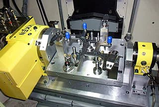
III. Selection of Structure
In mold processing, the tool structure selected varies with different processing stages. Both rough and precision machining stages have their specific tool structures to choose from.
Rough Machining Tool for Molds
Precision Tooling for Mold Manufacturing
Advanced tools can be utilized for the processing of small and medium-sized blanks, thus enhancing the quality and productivity of the operation. Large mold dimensions vary, and the requirements for rough and precision machining are different based on the part being processed. Appropriate vertical milling cutters are selected for use.
Whole vertical milling cutters are predominantly used in machining. For large mold processes, such as bumper injection cavities, the use of indexable insert machine clamping milling cutters is favored due to their cost-effectiveness and efficiency improvements. Precision machining, on the other hand, commonly employs whole vertical milling cutters.
Small-Scale Mold
Large-Scale Mold
IV. Characteristics of Rough/Semi-finish/Finish Machining
The primary goal of rough machining in die manufacturing is to maximize the metal removal rate per unit time, while preparing the geometric contours for semi-finishing. The main objective of semi-finishing is to achieve a smooth surface profile on the workpiece, ensuring an even allowance for the subsequent finish machining.
In both rough and semi-finish machining, larger feeds are used for efficient and economical processing, employing indexable insert milling cutters and high-feed high-speed milling cutters. The latter can operate under very high cutting parameters.
While the worktable feed is extremely high, the cut thickness is minimal, resulting in a large feed but small back cutting amount. Most of the cutting forces are generated axially, which can reduce vibration tendencies and achieve a high metal removal rate.
Key Points for the Selection of Milling Cutters in Roughing and Semi-Finishing of Different Surfaces
1. For rough machining of larger surfaces (flat or inclined), select indexable insert end mills, face mills, or high-speed feed mills.
2. For rough and semi-finished smaller surfaces, opt for end mills with round inserts. The larger radius of round inserts provides higher insert strength.
3. For roughing and semi-finishing of smaller surfaces, utilize indexable insert ball nose end mills. Willow leaf-shaped inserts can be chosen for their low cutting force and high machining efficiency.
During precision machining of curved surfaces, ball-end milling cutters are used. The radius of the cutter should be as large as possible to enhance tool rigidity, improve heat dissipation, and reduce surface roughness values.
Generally, the radius of curvature of a finely machined surface should be more than 1.5 times the tool’s radius to avoid abrupt changes in the feed direction.
However, when machining concave arcs, the radius of the milling cutter’s ball-end must be smaller than the minimum radius of curvature of the machined surface. Ball-end mills are used for semi-fine and fine milling of surfaces; small-diameter ball-end mills can perform fine milling on steep faces and small chamfers of straight walls.
However, when using a ball-end milling cutter to improve machining efficiency by increasing back-eating, noticeable cutting residues will remain on the machined workpiece after processing, increasing the workload for subsequent precision machining tools. Although rough machining efficiency is high, it reduces the efficiency of subsequent processes.
Small arc R milling cutter.
Small Diameter Milling Cutter
Key Points in Milling Cutter Selection for Precision Machining of Different Surfaces
1. For precision machining of larger surfaces, indexable insert ball nose end mills can be used to achieve high-accuracy machining. For smaller surfaces, solid ball nose end mills can be selected for high-precision machining.
2. High-precision machining of minute arc R parts.
3. For deep grooves and corners of minuscule width, small diameter solid carbide tools can be used in root clearing and corner cleaning operations for each workpiece.
As the founder of MachineMFG, I have dedicated over a decade of my career to the metalworking industry. My extensive experience has allowed me to become an expert in the fields of sheet metal fabrication, machining, mechanical engineering, and machine tools for metals. I am constantly thinking, reading, and writing about these subjects, constantly striving to stay at the forefront of my field. Let my knowledge and expertise be an asset to your business.
Ever wondered why the same CNC machine can have wildly different production efficiencies? The secret lies in the fixtures! In this article, we’ll explore how choosing the right CNC fixtures…
Have you ever wondered how to choose the best cutting tool for your CNC milling machine? This article dives into the essential properties and types of cutting tool materials, explaining…
Choosing the right coating for your cutting tools can significantly enhance their performance and longevity. But with various options available, how do you decide? This article dives into the different…
Why does one CNC machine tool outperform another? The answer often lies in the clamps used. This article explores the selection of appropriate clamps to enhance CNC machine tool efficiency.…
Choosing the right CNC machine can be daunting, given the array of models, systems, and specifications. This article simplifies the process, breaking down the selection into four key aspects: model…
Have you ever wondered which companies lead the milling machine industry? This article unveils the top 10 milling machine manufacturers of 2024, highlighting their innovations, global impact, and contributions to…
Have you ever wondered who leads the way in China's milling machine industry? This article showcases the top 10 milling machine manufacturers in China, revealing industry giants like WZ Wuhan…
Have you ever wondered about the giants of the CNC machine industry? In this fascinating blog post, we'll take a deep dive into the world of CNC manufacturing, exploring the…
In the rapidly evolving world of manufacturing, CNC machines have become indispensable. But with numerous manufacturers vying for attention, how do you choose the best? As an experienced mechanical engineer,…