Have you ever considered how hydraulic fixtures revolutionize automotive manufacturing? This article dives into the innovative design and advantages of hydraulic fixtures, focusing on their role in enhancing production efficiency and precision. By replacing mechanical components with hydraulic ones, these fixtures ensure reliable clamping and smooth operations. The piece also highlights specific solutions like the flywheel shell and gear cover hydraulic fixtures. Discover how these advancements reduce costs and improve manufacturing accuracy, transforming modern production lines.
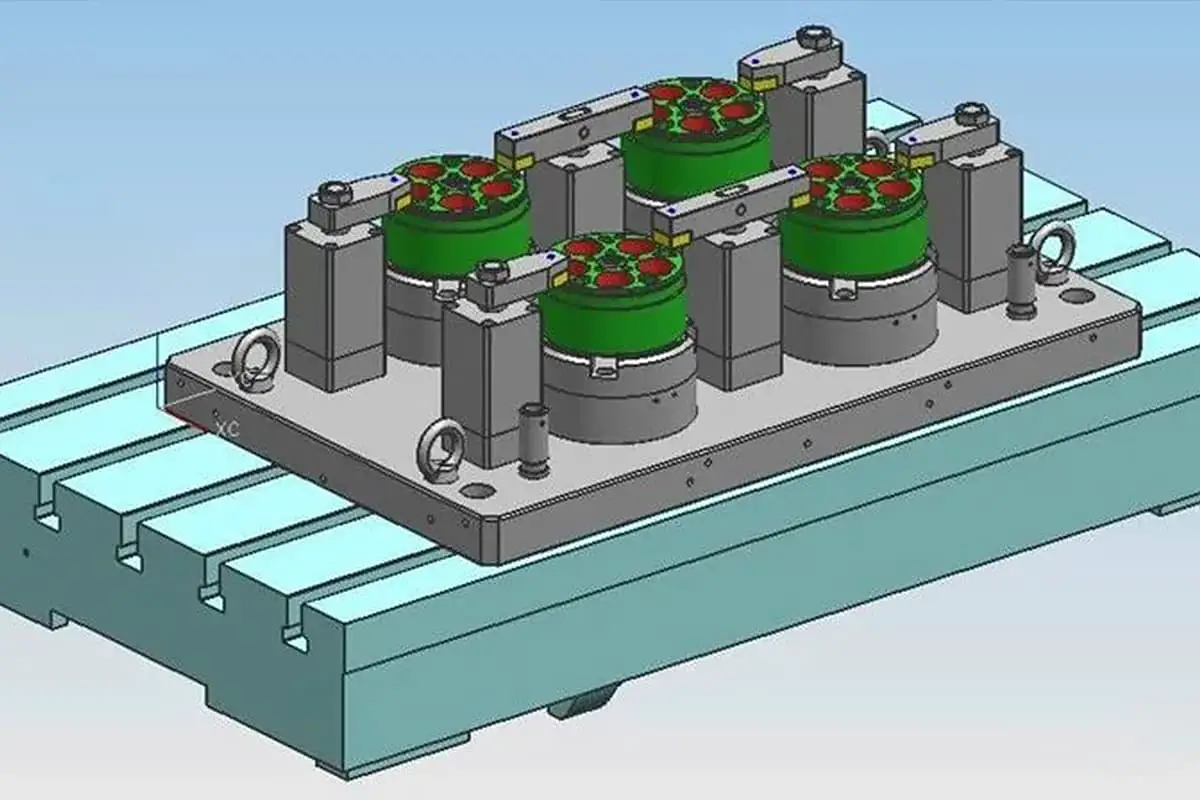
With the rapid development of the automotive industry, the progression of welding automation and the precision of production lines have increased, prompting businesses to raise their demands for the structure and functionality of welding fixtures.
Therefore, in the process of automotive welding automation, a rational jig and fixture structure facilitates the sensible arrangement of assembly line production, aids in balancing workstation time, and reduces non-productive time and production costs.
Hydraulic fixtures are devices that replace mechanical parts with hydraulic components to achieve automatic positioning, support, and clamping of the workpiece through hydraulic control.
They offer significant clamping force, reliable clamping, smooth operation, and user convenience, making them widely used in CNC machine tools, machining centers, and automated production lines. By assembling the selected hydraulic components with the designed mechanical parts, the necessary fixture can be obtained.

The design of hydraulic fixtures is a process of constant refinement and improvement. We are sharing two patent solutions today, specifically the detailed design and interpretation of the flywheel shell three-point centering hydraulic fixture and the gear cover hydraulic fixture, to enhance customers’ understanding of hydraulic fixture technology.
Problem addressed:
Currently, the centering of the machining fixture for the 10th sequence of the flywheel shell uses two fixed guide wheels and one spring-loaded floating guide wheel. Due to different casting batches of the workpiece blanks, there are significant size deviations, causing substantial discrepancies between the center of the hole at the workpiece’s positioning point and the fixture’s positioning center.
The fixture fails to perform its centering function, resulting in uneven hole wall thickness in the subsequent machining of the workpiece. This irregularity is excessive, leading to defective products.
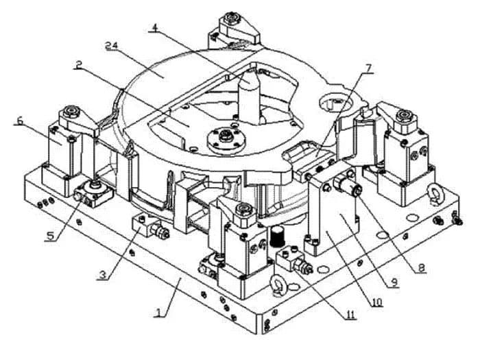
1. Fixture Base Plate
2. Three-Point Centering Component
3. Sequence Valve
4. Support Column
5. Support Cylinder
6. Swivel Cylinder
7. Angular Positioning Block
8. Pulling Cylinder
9. Vertical Plate
10. Angular Positioning Component
11. Sequence Valve
24. Workpiece
Technical Solution:
To overcome the aforementioned shortcomings, a flywheel casing three-point hydraulic fixture is designed. Through the pushing cylinder, three evenly distributed guide rods are driven, enabling the positioning heads on the guide rods to be centered.

1. Fixture Base Plate
2. Three-Point Centering Component
3. Sequence Valve
4. Support Column
5. Support Cylinder
6. Angle-turning Cylinder
7. Angular Locating Block
8. Pull Cylinder
9. Vertical Plate
10. Angular Positioning Component
11. Sequence Valve
Technical characteristics:
The flywheel case’s three-point hydraulic centering fixture comprises the following parts in sequence: fixture base plate, three-point centering component, sequence valve A, sequence valve B, support column, support cylinder, angle-turning cylinder, and the angular positioning component.
The three-point centering component is installed on the fixture base plate, and the positioning head is placed on the same arc by adjusting the adjustment pad. The positioning head is centered by pushing three evenly distributed guide rods by the push cylinder.
The sequence valves, support column, support cylinder, and angle-turning cylinder are all mounted on the fixture base plate. The angular positioning component is installed on the fixture base plate with the pull cylinder set on the vertical plate connected to the angular locating block.

1. Fixture base plate
2. Three-point centering component
4. Support post
10. Angular positioning component
12. Positioning head
13. Adjusting pad
14. Positioning guide bush
15. Three-point positioning seat
16. Spring
17. Bushing
18. Guide rod
19. Centering sleeve
20. Push cylinder
21. Push rod
22. Spring
23. Thrust flange
24. Workpiece
Usage:
Place the workpiece on the support post in the direction of angular positioning. At this moment, the hydraulic station solenoid valve is in the middle position for unloading, and the angular positioning block is inserted into the slot on the workpiece for positioning.
After the oil circuit is filled with oil, the push cylinder in the three-point centering component pushes the push rod, causing the positioning head on the guide rod to move and contact the workpiece positioning surface to achieve three-point centering positioning.
Then, through the sequence valve, the support cylinder rises to fix. Through the sequence valve again, the angle cylinder presses the workpiece. After the workpiece is processed, the oil circuit is unloaded, and at this time, the pull cylinder in the angular positioning component pulls back the angular positioning block, disengaging the workpiece.
The push cylinder in the three-point centering component retracts, the push rod retracts under the action of the spring, the guide rod drives the positioning head to retract under the action of the spring, and the positioning head disengages from the workpiece.
Issue:
Currently, the gear cover manufacturing process relies on the large hole in the raw workpiece for positioning. The top surface and holes are then machined, followed by using the finished holes for positioning to drill the raw workpiece. This requires two sets of fixtures and results in high costs due to the processing steps involved.

1. Fixture plate
2. Auxiliary support cylinder
3. Corner turn cylinder
4. Positioning disc assembly
5. Support column
6. Lever cylinder
7. Sequence valve
8. Support cylinder
9. Pull cylinder
10. Rough positioning rod
11. Latch
12. Elastic positioning pin
Technical solution:
Design a gear cover hydraulic fixture that uses the large hole in the workpiece blank as the positioning hole and processes the blank large hole in this sequence. The positioning of the workpiece blank large hole is composed of the positioning disc assembly and the pull cylinder.
After the workpiece is positioned and clamped, the pull cylinder pulls the positioning disc away from the positioning hole, while the auxiliary support cylinder rises and clamps.

Technical Characteristics:
The pull cylinder is located within the positioning disk assembly; auxiliary support cylinder, angle-turning cylinder, positioning disk assembly, support column, lever cylinder, sequence valve, support cylinder, coarse positioning rod, latch and elastic positioning pin assembly are all mounted on the fixture plate; the sequence valve controls the pull, drawdown, and clamping functions of the pull cylinder, lever cylinder, and auxiliary support cylinder; the latch manages the position between the fixture plate and the worktable.

2. Auxiliary Support Cylinder
3. Angle Rotation Cylinder
6. Lever Cylinder
7. Sequence Valve
8. Support Cylinder
9. Pull Cylinder
Usage Process:
The workpiece is placed on the support pillar along the rough positioning rod on the fixture plate. The hole in the workpiece is inserted onto the positioning disc assembly and the elastic positioning pin assembly. The angle rotation cylinder clamps the workpiece, and at the same time, the support cylinder clamps it.
Through the sequence valve, the lever cylinder clamps, and the auxiliary support cylinder pushes up to clamp, while simultaneously, the pull cylinder pulls down the positioning disc on the positioning disc assembly, disengaging from the workpiece.

