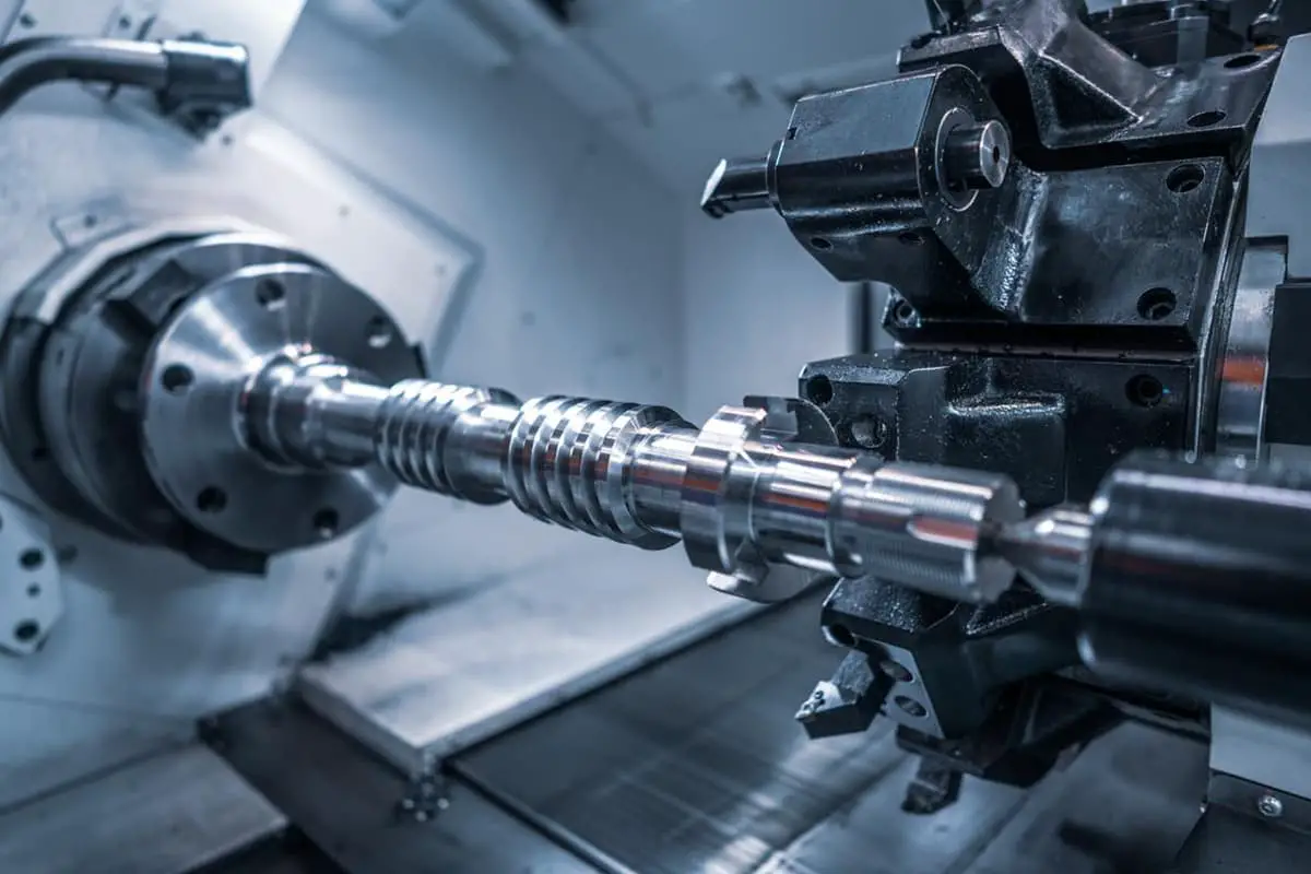
In this article, we’ll explore essential formulas for trigonometry, cutting speed, feed rates, and more. You’ll gain practical insights to enhance your machining efficiency and accuracy. Get ready to unlock the secrets behind seamless metalworking!
1.tgθ=b/a ctgθ=a/b
2.Sinθ=b/c Cos=a/c
Vc=(πDS)/1000
F=SZFz
Scallop=(ae*ae)/8R
Φ=√2R2
X. Y=D/4
Q=(aeapF)/1000
Fz=hm * √(D/ap )
Tooling depth = plate thickness – tool height + drill tip (0.3D)
T(min)=L(min)/N(rpm)*f(mm/rev)=πDL/1000vf
Drill factor table fz
| Dia. mm | Feed knife mm/rev |
| 1.6~3.2 | 0.025~0.075 |
| 3.2~6.4 | 0.05~0.15 |
| 6.4~12.8 | 0.10~0.25 |
| 12.8~25 | 0.175~0.375 |
| >25 | 0.376~0.625 |
1 inch = 25.4 mm.
Below are answers to some frequently asked questions:
The formula for calculating cutting speed in CNC machining is:
Where:
For example, if you are machining a workpiece with a diameter of 25 mm at a spindle speed of 4500 rpm, the cutting speed would be calculated as follows:
To convert this to meters per minute, divide by 1000:
This formula is essential for optimizing machining processes, ensuring efficiency, tool longevity, and achieving the desired surface finish.
To determine the rotation speed (RPM) for a CNC machine, you use the formula:
where ( N ) is the rotational speed in revolutions per minute (RPM), ( Vc ) is the cutting speed in meters per minute (m/min), and ( D ) is the diameter of the tool in meters (m). For example, if the cutting speed ( Vc ) is 100 m/min and the tool diameter ( D ) is 0.025 m (25 mm), the calculation would be:
This formula ensures that you achieve the correct rotational speed based on the cutting speed and tool diameter, which is crucial for precise machining.
The key variables in calculating feed rate for CNC operations are:
These variables are essential for determining the appropriate feed rate, ensuring precise and efficient machining.
Cutting power in CNC machining is calculated using the formula:
Pc = MRR × k
where ( Pc ) is the cutting power, ( MRR ) (Material Removal Rate) is the volume of material removed per unit time, and ( k ) is the specific cutting force.
To break it down further:
An example calculation: For a machining operation with a depth of cut ( ap ) of 3 mm, a feed rate ( f ) of 0.2 mm/rev, and a cutting speed ( Vc ) of 120 m/min, if the specific cutting force ( k ) for the material is 3100 MPa, the cutting power ( Pc ) can be calculated as follows:
This simplified example illustrates the core concept of calculating cutting power in CNC machining, ensuring efficient and precise operations.
In CNC machining, several key formulas are used for thread calculations to ensure precision and compatibility. These include:
Thread Pitch Calculation:
where ( P ) is the thread pitch, ( L ) is the thread length, and ( n ) is the number of threads.
Core Hole Diameter Calculation:
where ( d_4 ) is the core hole diameter, ( D ) is the nominal diameter, and ( P ) is the pitch.
Bore Diameter Calculation for Tapping:
Thread Depth Calculation:
Metric Threads:
British Standard Whitworth (BSW) Threads:
Pitch Diameter Calculation:
where the coefficient for a 60° tooth profile is typically 0.6495.
Minor Diameter Calculation:
These formulas are essential for accurate and precise thread calculations in CNC machining, covering various aspects such as thread pitch, core hole diameter, thread depth, pitch diameter, and minor diameter.
The theoretical surface roughness in CNC operations is calculated using the formula
where ( h ) is the theoretical surface roughness, ( f ) is the feed per revolution, and ( Re ) is the insert’s corner radius. For example, if the feed per revolution ( f ) is 0.1 mm/rev and the insert’s corner radius ( Re )) is 0.5 mm, the calculation would be
This calculation helps in determining the expected smoothness of the machined surface based on the cutting parameters and tool geometry.

