Are you struggling with CNC machining quality? Discover how small tweaks in your process can yield big improvements. This article delves into ten expert tips that cover everything from tool selection to clamping methods, ensuring higher precision and efficiency in your machining projects. By the end, you’ll have practical insights to enhance your CNC operations and produce superior results.
“CNC Machining” refers to the use of numerical control machining tools.
As it is controlled by computer programming, CNC machining offers several benefits such as consistent quality, high precision, high repetition accuracy, ability to machine complex surfaces, and increased efficiency.
However, it’s worth noting that the final quality of the machined product can be greatly impacted by human factors and operator experience during the actual machining process.
Let’s now take a look at ten valuable machining tips, as summarized by a CNC machine operator with over a decade of experience in the field.
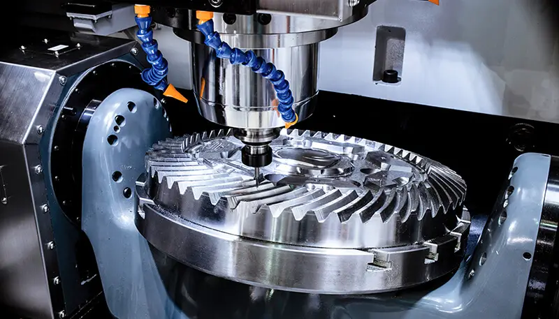
The division of CNC machining processes can generally be carried out using the following methods:
Tool-Centered Sorting Method
The tool-centered sorting method is to divide the processes based on the tools used and to use the same tool to machine all parts that can be completed. The second and third knives are utilized to complete other parts they can finish. This approach reduces the number of tool changes, minimizes idle time, and decreases unnecessary positioning errors.
Sorting by Processing Position
For parts with many CNC processing steps, the processing part can be divided into several sections based on its structural characteristics, such as inner shape, outer shape, curved surface, or plane, etc. Generally, the plane and positioning surface are machined first, followed by holes; simple geometries are machined before complex ones; and low precision parts are processed before those with high precision requirements.
Sorting by Rough and Fine CNC Machining
For parts that are prone to deformation during rough and fine CNC machining, the shape needs to be calibrated due to possible deformation after rough machining. Therefore, the processes are generally separated for rough and fine machining.
In conclusion, when dividing the process, it’s important to consider the structure and manufacturability of the parts, the function of the machine tool, the NC machining quantity of the parts, the installation times, and the production organization of the unit. Additionally, the principle of process concentration or dispersion should be determined based on the actual situation, but it must be reasonable.
The machining sequence should be planned based on the structure and condition of the parts, as well as the positioning and clamping requirements, with a focus on avoiding damage to the rigidity of the workpiece. The following principles should be followed when arranging the sequence:
When determining the positioning datum and clamping scheme, the following four points should be taken into consideration:
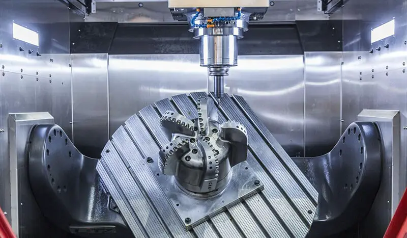
The tool setting point can be established on the machined component, but it’s important to note that the tool setting point should be a reference position or the final product. In some cases, after the first machining process, the tool setting point may become damaged, making it difficult to locate the tool setting point in subsequent processes.
To avoid this, care should be taken to set a relative tool setting position in the first process that has a consistent relationship with a reference benchmark. This way, the original tool setting point can be identified based on the relative relationship between them.
This relative tool setting position is often located on the machine tool workbench or fixture, and the selection should take into account the following principles:
The starting point of the workpiece coordinate system is established by the operator. Once the workpiece is securely fastened, the tool setting defines its position. This defines the distance between the workpiece and the machine tool’s zero point.
Once the workpiece coordinate system has been established, it typically remains unchanged. To ensure accurate machining, it is important that the workpiece coordinate system and the programming coordinate system are in sync, meaning they are consistent with each other during the machining process.
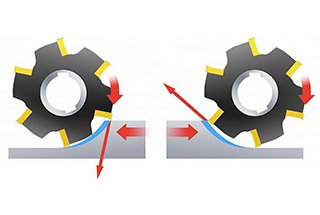
The tool path refers to the path and direction of the tool movement relative to the workpiece during NC machining. The selection of the cutting path is crucial as it impacts the accuracy and surface quality of the machined parts.
The following factors are taken into consideration when determining the cutting path:
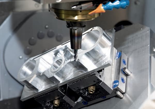
Once the workpiece is properly aligned and the program has been thoroughly debugged, it can proceed to the stage of automatic machining.
During this stage, the operator should closely monitor the cutting process to ensure that the workpiece quality is not compromised and to prevent any accidents that may occur as a result of abnormal cutting.
The following aspects should be taken into consideration when monitoring the cutting process:
(1) During the rough machining stage, the focus of the machining process monitoring is mainly on the swift removal of excess material from the surface of the workpiece.
In the operation of the machine tool, the cutting process is carried out automatically according to the predetermined cutting path and cutting parameters set by the operator.
The operator should closely monitor the changes in the cutting load throughout the process by checking the cutting load table. Based on the tool’s bearing force, the cutting parameters should be adjusted to maximize the efficiency of the machine tool.
(2) Monitoring of Cutting Sound During Cutting Process
During the automatic cutting process, when the cutting process begins, the sound of the tool cutting the workpiece is generally stable, continuous, and light.
At this stage, the movement of the machine tool is stable. However, as the cutting process progresses, issues such as hard spots on the workpiece, tool wear, or improper tool clamping can cause the cutting process to become unstable.
Indicators of instability include changes in the cutting sound, tool-workpiece collision, and machine tool vibration. In these cases, the cutting parameters and conditions should be promptly adjusted.
If the adjustment does not yield the desired result, the machine tool should be stopped to inspect the condition of the tools and workpieces.
(3) Monitoring the Finishing Process to Ensure Workpiece Machining Size and Surface Quality
During the finishing process, the cutting speed is high and the feed rate is large. Attention should be given to the impact of chip buildup on the machined surface.
For cavities that are being machined, it is important to be aware of over-cutting and tool wear at corners.
To address these issues, the following steps can be taken:
If these adjustments are not effective, it may be necessary to stop the machine and evaluate the reasonableness of the original program.
It is important to pay attention to the position of the tool when pausing the inspection or stopping the machine. If the cutting tool stops in the middle of the cutting process, sudden cessation of the spindle can result in tool marks on the workpiece surface.
In general, it is recommended to turn off the machine when the tool is no longer in a cutting state.
(4) Tool Monitoring: Tool Quality Impacts Workpiece Machining Quality
The quality of the tool plays a major role in determining the machining quality of the workpiece.
During the process of automatic machining and cutting, the normal wear and any abnormal damage to the tool can be detected through sound monitoring, control of cutting time, inspections during the cutting process, and analysis of the workpiece surface.
To ensure that the machining quality meets the required standards, the cutting tools should be managed in a timely manner to prevent any processing quality issues caused by improper handling of the tools.
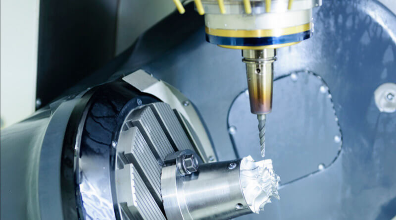
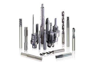
(1) For plane milling, it is recommended to use a non-reground carbide end mill or end mill cutter. When milling in general, it is best to use the second tool feeding whenever possible. For the first tool feeding, it is recommended to use an end mill cutter for rough milling and continuously feed along the surface of the workpiece. The recommended width of each tool feeding should be between 60% to 75% of the tool diameter.
(2) End mills and end mills with carbide inserts are primarily used for processing bosses, grooves, and box mouth surfaces.
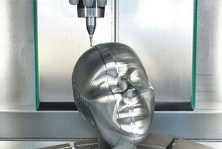
(3) Ball cutters and round cutters (also known as round nose cutters) are commonly used for processing curved surfaces and variable angle contours. Ball cutters are mainly used for semi-finishing and finishing, while circular cutters with cemented carbide are mostly used for roughing.
(1) The machining program list is an essential component of the NC machining process design. It serves as a procedure that must be followed and executed by the operator. The machining program list provides a detailed description of the machining program and is used to clarify the content of the program, the clamping and positioning method, and the tools selected for each machining program, among other things.
(2) The machining program sheet should include the following information: the name of the drawing and programming file, the name of the workpiece, a sketch of the clamping method, the name of the program, the tools used in each program, the maximum cutting depth, the nature of the machining (such as rough or finish), and the theoretical machining time.
Before programming, it is important to consider the following after determining the processing technology:
The principle of setting the safety height is to ensure that it is generally higher than the highest surface of the workpiece or to set the programming zero point to the highest surface. This helps to minimize the risk of tool collision.

