Ever wondered how metal is cut without overheating? Cold saws, using circular blades, transfer heat to the sawdust instead of the workpiece, keeping both cool. This method allows for precise, burr-free cuts, ideal for various metalworking applications. In this article, you’ll learn about the types of cold saw blades, their cutting speeds, and the advantages of using cold saws, including improved accuracy, reduced material stress, and longer blade life. Dive in to discover how cold saws can enhance your metal cutting processes.
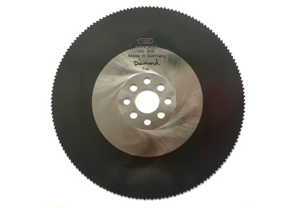
A cold saw, also known as a metal cutting cold saw, is a precision metal-cutting tool that utilizes a circular blade for efficient and accurate material processing. This cutting method derives its name from its unique thermal management characteristics during operation. As the saw blade’s teeth engage the workpiece, the majority of the heat generated is efficiently transferred to the metal chips (often referred to as swarf in machining terminology), rather than being absorbed by the workpiece or the blade itself.
This heat dissipation mechanism offers several advantages:
Cold saw blades are primarily categorized into two types: High-Speed Steel (HSS) blades and Tungsten Carbide-Tipped (TCT) alloy blades. Each type offers distinct advantages for various cutting applications.
HSS blades are typically manufactured from M2 or M35 grade steel. Their cutting speeds range from 10 to 150 meters per minute, varying based on the workpiece material and dimensions. Advanced coated HSS blades can achieve cutting speeds up to 250 meters per minute, offering enhanced performance.
The tooth feed rate for HSS blades spans 0.03 to 0.15 millimeters per tooth, contingent upon the sawing equipment’s power, torque, and overall quality. HSS blades are available in outer diameters from 50 to 650 millimeters, with a standard hardness of HRC 65.
A key advantage of HSS blades is their ability to be resharpened, typically allowing for 15 to 20 sharpening cycles depending on the workpiece specifications. For larger HSS blade specifications, the cutting life can extend to 0.3-1 square meter of cutting end face area.
For blades exceeding 2000 millimeters in diameter, a composite construction is often employed. This involves HSS inlays for the saw teeth, while the blade body is constructed from vanadium or manganese steel, optimizing performance and durability.
TCT blades feature cutting edges made from tungsten carbide, a material known for its exceptional hardness and wear resistance. These blades operate at cutting speeds between 60 and 380 meters per minute, adapting to various workpiece materials and dimensions. The tooth feed rate for TCT blades ranges from 0.04 to 0.08 millimeters per tooth.
TCT blades are commonly available in diameters from 250 to 780 millimeters. For cutting ferrous materials, two distinct TCT blade designs are prevalent:
1. High-Speed, Fine-Toothed Blades:
2. Heavy-Duty, Coarse-Toothed Blades:
The choice between HSS and TCT blades, as well as specific blade designs within each category, depends on factors such as workpiece material, size, cutting speed requirements, and the desired balance between initial cost and long-term efficiency.
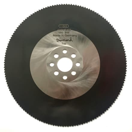
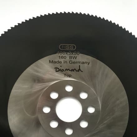
(Compared with Manganese Steel Flying Saw)
Cold saw cutting and friction sawing differ significantly in their cutting mechanisms and resultant effects:
Manganese steel flying saw: This method employs a high-speed rotating manganese steel blade that generates substantial friction with the workpiece. The intense heat produced at the contact point causes localized melting and subsequent separation of the welded pipe. This process is essentially a controlled burn-through, characterized by visible scorch marks on the cut surface and potential microstructural changes in the heat-affected zone.
High-speed steel cold cut saw: In contrast, this technique utilizes a slower-rotating high-speed steel blade to perform a milling-like cutting action on the welded pipes. The controlled cutting speed and superior edge retention of HSS blades result in a smooth, precision cut with minimal burr formation. This method produces significantly less heat, preserving the material’s microstructure and mechanical properties near the cut. Additionally, the cold cutting process operates with notably reduced noise levels compared to friction sawing.
The choice between these methods depends on factors such as material properties, desired cut quality, production speed requirements, and downstream processing needs. Cold saw cutting generally offers superior cut quality and tighter tolerances, making it preferable for applications demanding high precision or where post-cut finishing operations need to be minimized.
The high-speed steel cold cut saw offers significant advantages in metal pipe cutting:
Cutting Efficiency: The saw achieves optimal cutting speeds, resulting in high work efficiency and productivity.
Precision and Quality: The blade exhibits minimal deviation, producing cuts with negligible burrs on the steel pipe surface. This enhances workpiece cutting accuracy and maximizes blade longevity.
Thermal Stability: Utilizing a cold milling and cutting method, the process generates minimal heat. This preserves the internal stress distribution and material structure of the cut section, avoiding undesirable alterations. The blade exerts minimal pressure on the steel pipe, preventing deformation of the pipe wall and mouth.
Superior End Face Quality:
Operator Ergonomics: The process induces low operator fatigue, contributing to sustained cutting efficiency over extended periods.
Environmental and Safety Benefits: The cutting process produces no sparks, dust, or excessive noise, making it environmentally friendly and energy-efficient.
Cost-Effectiveness and Longevity: The blade can be repeatedly sharpened using a specialized grinding machine, maintaining performance equivalent to a new blade. This feature significantly improves production efficiency and reduces operational costs.
Optimize sawing parameters based on the material properties and specifications of the workpiece:
Vibration problem and its treatment
During the cutting process, there is a tendency for vibration to occur which can lead to poor cutting effect, long equipment downtime, blade breakage during the cutting process or other occurrences such as bearing burn caused by uneven pressure on the spindle. The surface size and burr of the steel cut by sawing are out of tolerance.
Measures taken:
(1) Conventional method: In the installation process, leveling is adopted (set the horizontal position of the upper slide support and lower idler wheel based on the reference point), and the V-shaped wheels are aligned in a straight line using a wire drawing method, so that the idler wheel is at a uniform height and on the same line. Based on the force analysis of the upper slide support, counterweights are added to the saw cover area to balance the force and ensure stable operation.
Stacking problem of steel and its treatment
During the cutting process, if the stress is uneven, the steel may stack, especially when cutting small-sized steel, which can cause damage to the saw blade and equipment.
Measures taken:
(1) An air pressure-driven torque clamping device is installed in the cutting port to eliminate the stacking phenomenon, protect the saw blade, and reduce the reactive force generated by deformation of the steel under radial force acting on the saw blade.
(2) Support rollers are added to the cutting port, and after increasing the support rollers, they work together with the clamping device to pressurize the steel before cutting. This significantly improves the surface quality of the saw cut and greatly reduces the damage rate of the saw blade.
The problem of large water spray area and its treatment
When entering the cold saw, round steel is around 320℃, and water is sprayed to cool the saw blade during the cutting and withdrawal processes. In actual production, the water spray area is too large, which causes a decrease in the surface quality of the steel and water waste.
Measures taken:
(1) The original sprinkler pipe is replaced with a spray pipe. More nozzles are added, and a fog spray method is used for key spraying at the cutting point. Since the nozzle end has a circular arc concave surface, it can atomize the water mist, make the spray uniform, and is easy to replace due to the use of screw connections, which is conducive to maintenance work.
(2) Use the surrounding cooling method to cool the saw cover, and spray-cool the cutting port and cutting teeth in a targeted manner on key parts.
(3) When feeding during sawing, a spray valve is used, and the injection pressure is increased. The spray valve is closed during withdrawal.
Friction problem between the saw cover and the saw blade and its treatment
The friction between the saw cover and the saw blade causes the overall vibration of the upper slide support, which results in loosening of the motor grounding bolt, and if this goes on for a long time, it will directly cause bearing burn or motor burn.
Measures taken:
(1) The connection method of the original saw cover spindle was unreasonable, and the stress point of the saw cover pin shaft was on one side plate of the upper slide support, which easily deformed the side plate and caused the saw cover to tilt. By lengthening the pin shaft and increasing the stress point, using the side plate as a fulcrum, and making the internal panel of the upper slide support the real stress point, the structure of the saw cover became more reasonable, avoiding similar accidents.
(2) When replacing the saw blade, the original method of using a crane to lift the saw cover can easily deform the cover. Now hydraulic cylinders are used to lift the saw cover, and cushion pads are added where the cover contacts with the steel after the saw cover is flipped, which effectively solves the problem.

