As an engineer, you know that the devil is in the details when it comes to designing and manufacturing machinery. One crucial aspect that can make or break the quality of your final product is the use of profile parts. These seemingly simple components play a vital role in determining the strength, durability, and aesthetic appeal of your machinery frames. However, the production of profile parts is not without its challenges. Defects can arise at various stages of the manufacturing process, leading to subpar products that fail to meet your exacting standards. In this blog post, we’ll take a deep dive into the most common defects found in profile products and explore practical solutions to help you mitigate these issues. By the end of this article, you’ll have a better understanding of how to ensure the quality and integrity of your profile parts, setting the stage for the creation of truly exceptional machinery.
Under the same conditions, as profiles themselves have better mechanical properties compared to sheet materials, the frames they form often feature characteristics such as lightness, high strength, and aesthetic appeal. Additionally, with the development of domestic manufacturing processes and the gradual improvement of manufacturing capabilities, various types of profile parts are now widely used to produce product frames for cabs of various engineering machinery and agricultural machinery products.
Although profiles have more advantages over plates in the frame structure, profiles are actually secondary processed products of plates. During the production of profile raw materials and parts, more defects are inevitably produced compared to plates. By analyzing the mechanism of these defects, and designing in advance to eliminate or mitigate them, production risks can be greatly reduced.
The following examples will explain the analysis from the two aspects of raw material production and pipe bending production.
The profile processing technology is now relatively mature. According to our company’s experience in recent years, the defects of profile raw materials that have a significant impact on subsequent production are mainly concentrated on three aspects: incomplete cross-sectional shape, scratches, and twisting. The following are examples for detailed explanation.
(1) Incomplete cross-sectional shape.
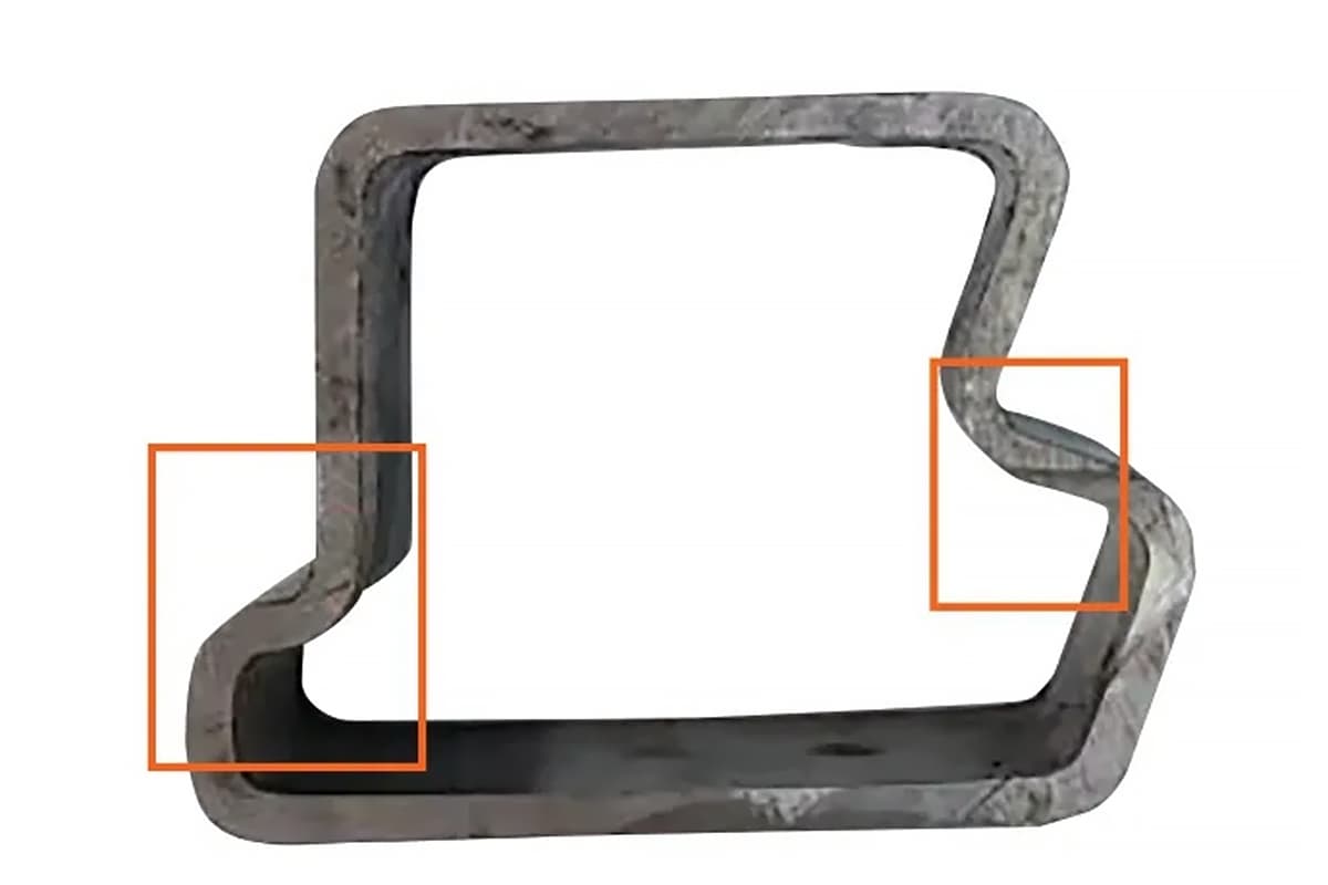
Taking our company’s special-shaped pipe used in the cab of construction machinery as an example, part of the cross-section is shown in Figure 1.

As shown in the red frame in Figure 1, due to the relatively large deformation of the material at this position, when the round-to-roll forming process is adopted, this position cannot deform according to the theoretical design. The actual cross-section of this position is shown in Figure 2.
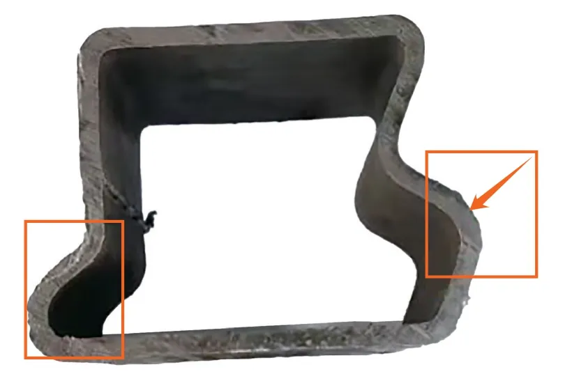
From Figure 2, it can be seen that the deformation in the red frame position is not sufficient and does not meet expectations. Analysis shows that when using round-to-roll forming, the strip raw material is first formed into a round pipe in the front half of the rolling line. In the second half, the cross-section of the round pipe is plastically deformed into the required cross-section through rolling molds. In case of significant local variation in profile cross-section, the material cannot flow well with the rolling mold due to the internal stress of the round pipe itself, resulting in an incomplete shape after forming, thus affecting the use of the profile in the whole machine.
For similar cross-sections, it is best to use drawing or step-by-step rolling forming processes during the processing of profile raw materials. Figure 3 shows the drawn forming of a special-shaped pipe.
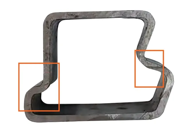
It can be seen that under this state, each position in the cross-section is relatively complete, especially in the red frame area. The quality is significantly improved compared to the round-to-roll forming.
(2) Surface scratches.
As long as the material undergoes processing deformation, scratches may exist. The common causes and solutions for scratches are as follows.
(i) Insufficient surface hardness of the mold, resulting in wear during production, increasing surface roughness, and causing scratches on the surface of the raw material.
The solution is to regularly reinspect the surface hardness of the mold, and promptly perform surface treatment and polishing.
(ii) Presence of iron filings and other impurities on the mold surface, causing hard contact with the strip surface and resulting in scratches.
The solution is to promptly inspect the finished raw materials, clean the mold after discovering scratches, and control the raw materials to reduce the use of flaky raw materials.
(iii) Inconsistency in the gap between borrowed and newly made molds resulting in scratches. This phenomenon is relatively special. When profiles adopt the roll forming process, dozens of sets of rollers are often needed. To reduce production costs, manufacturers may borrow existing molds for some stations and only make molds for stations that cannot be borrowed. Inconsistent wear degrees between new and old molds will result in different mold gaps, possibly causing material extrusion and surface scratches of the strip during deformation.
This phenomenon cannot be well improved during production; it can only be reviewed at the initial mold design stage to avoid such occurrences by evaluating the status of the molds being borrowed.
(3) Profile twisting.
This phenomenon is explained from the perspectives of drawing and roll forming.
(i) Drawing forming.
Due to the comparatively lower initial investment and shorter development cycle, drawing still has a wide range of applications in some industries. However, due to the inherent defects of the drawing process, two or three drawing operations are usually needed to obtain the required cross-section, and heat treatment or aging treatment is needed after each drawing to eliminate the residual stress in the raw material. This leads to poor straightness of the raw material produced by the drawing process, and for environments with relatively high requirements, a correction process needs to be added to resolve this defect.
(ii) Roll forming.
Whether using round-to-roll or step-by-step forming, both require dozens of roll forming molds on the production line. In actual production, if the centerlines of the rolling molds are not aligned, it will cause the profile to twist after production.
After the twisting phenomenon occurs, it is necessary to analyze and determine the possible problematic rolling mold positions based on the deformation trend of the profile on the line, and then adjust the molds according to the deformation degree to eliminate the defect. In addition, auxiliary tools such as threads can be used during mold installation to ensure the mold center is aligned with the equipment center, which can greatly reduce the possibility of twisting.
After the processing of profile raw materials, they need to be bent into pipes to obtain the required part shape before use. During this process, three defects often occur: springback, twisting after bending, and surface scratches. The following is an explanation for each defect.
(1) Springback.
The frame structure, such as the cab, often uses cold-formed hollow sections. During the pipe bending process, there are two types of deformation: elastic and plastic deformation. After bending, springback often occurs, causing the dimensions to deviate from the theoretical values. This phenomenon results from the combined action of springback in terms of angle and radius. For example, the part shown in Figure 4.
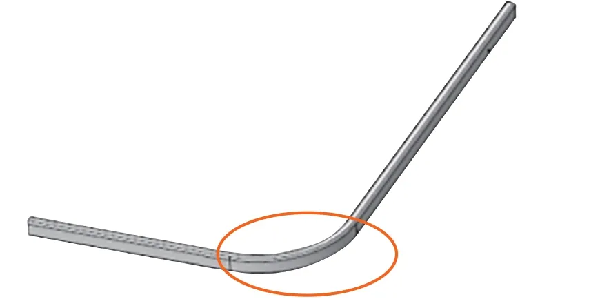
The part shown in the figure requires a bending radius of R206mm and an angle of 90°. During the first production of the bending mold, it was designed and manufactured according to the theoretical value of R206mm. In actual production, after setting the bending angle to 90° and using the mold to pull the bend into shape, the actual part had an angle of 84° and a radius of R223mm. There was a large gap between the radius of the part and the theoretical value, and the angle did not match the drawing. This part could not be used. Later, based on previous bending experience and the deviation between the actual and theoretical radii, the bending angle was set to 98°, and the bending mold was redesigned to a radius of R193mm. The redesigned part status is shown in Figure 5.
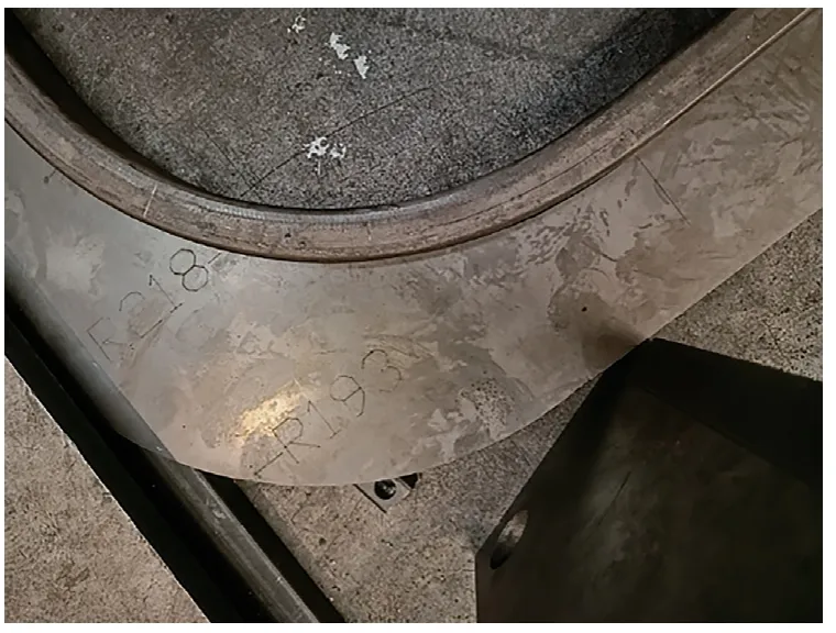
As can be seen from the figure, the gap between the R-corner and the inspection template is within 1mm. This state meets the requirements for subsequent production.
For this type of pipe and bending angle, the rebound coefficient is roughly 8%. Since the profile is cold-bent hollow steel, its rebound coefficient cannot be strictly based on the empirical values of steel plates. Additionally, the performance of raw materials in each batch cannot be completely consistent. Therefore, it is necessary to summarize based on actual usage experience. It is also recommended that raw material manufacturers use strip steel from the same manufacturer and the same batch for profile production as much as possible to stabilize the raw material state of the profile.
(2) Twisting after bending the pipe.
This condition mostly exists in parts with a large arc push bend. This phenomenon is largely due to the mold design, and the pipe type is shown in Figure 6.
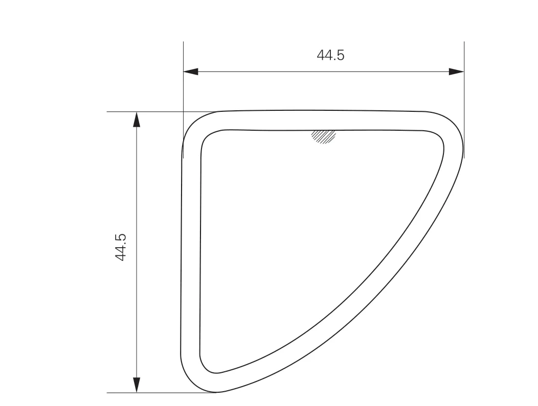
The impact of the asymmetry of the pipe type on the pipe bending was not identified in the mold design process. In the actual mold design, the main roller and the clamping roller are shown in Figure 7.
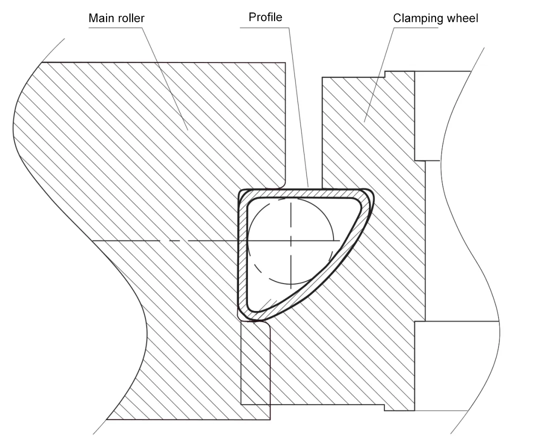
Because the clamping roller compresses too little, failing to exceed the centerline of the profile, it leads to insufficient edge compression force on the profile during production. The profile twists around the centerline during bending, causing the actual bent part to have unacceptable flatness and be unusable. The size of the edge compression ring of the clamping roller was later changed so that it exceeded the centerline of the pipe, as shown in Figure 8.

Based on the modified mold, during the bending process, the edge compression force range of the clamping roller exceeds the centerline of the pipe. The flatness of the pipe after bending has significantly improved under this condition, now meeting the usage requirements.
(3) Surface scratches.
The causes of this defect mainly come from two aspects: misalignment between the mold cavity and the raw materials, and low surface hardness of the mold.
The solution is to calculate the tolerance matching between the mold design and raw material development to avoid the condition where the cross-sectional size of the raw material exceeds the mold cavity. At the same time, the mold surface needs timely treatment to increase hardness while reducing surface roughness.
This article analyzes and explains common defect issues from two aspects: the processing of profile raw materials and the subsequent processing of parts. However, this is only limited to the use conditions of our company. Since the performance of profiles compared to plates is more prominent, and different manufacturers may use different raw materials and processing techniques, actual situations may vary. It is necessary to summarize based on one’s own usage experience to obtain a suitable on-site production plan.

