Why do cracks form in die steel during quenching, and how can they be prevented? This article explores the different types of cracks that can occur, from longitudinal to stress corrosion cracking, and provides a detailed analysis of the causes behind each type. Learn about the essential preventive measures, such as material selection and heat treatment techniques, to ensure the integrity and longevity of die steel components in your manufacturing processes.
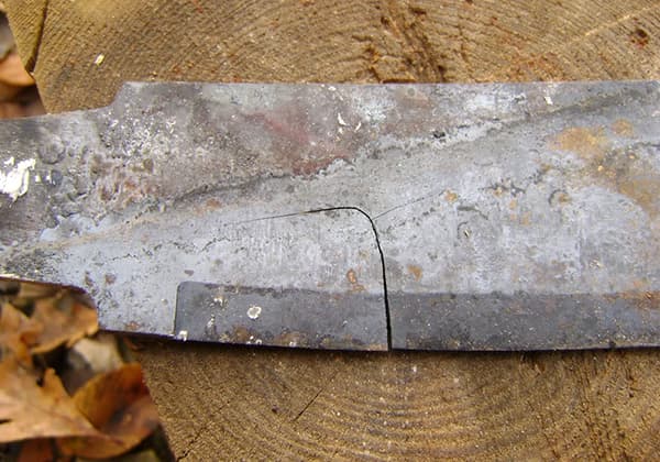
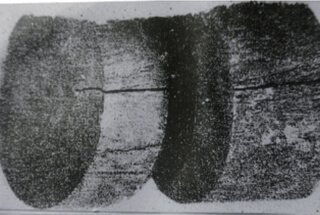
Longitudinal cracks in dies are characterized by their axial orientation, thin profile, and elongated shape. These defects typically occur during the quenching process, particularly in centerless quenching, where the entire die undergoes rapid cooling.
During centerless quenching, the core of the die transforms into martensite, a hard but brittle microstructure with the largest specific volume compared to other steel phases. This volumetric expansion generates significant tangential tensile stresses within the die.
The magnitude of these internal stresses is directly proportional to the carbon content of the die steel. Higher carbon steels experience greater martensitic transformation, resulting in more pronounced volumetric changes and, consequently, higher tangential tensile stresses.
When these internal tensile stresses exceed the ultimate tensile strength of the steel, longitudinal cracks form. These cracks propagate along the axis of the die, following the path of maximum stress concentration.
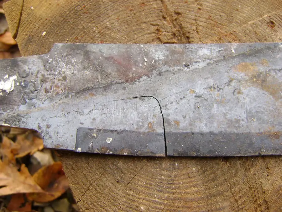
The following factors aggravate the generation of longitudinal cracks:
(1) The steel contains a lot of S, P, Bi, Pb, Sn, As and other harmful impurities with low melting point.
When the steel ingot is rolled, it presents a serious longitudinal segregation distribution along the rolling direction, which is easy to produce stress concentration and form longitudinal quenching cracks, or the longitudinal cracks formed by rapid cooling after raw material rolling are not processed and retained in the product, causing the final quenching cracks to expand and form longitudinal cracks;
(2) Longitudinal cracks are easy to form when the die size is within the range of quenching crack sensitive size of steel (the dangerous size of quenching crack of carbon tool steel is 8-15mm, and the dangerous size of medium and low alloy steel is 25-40mm) or the selected quenching cooling medium greatly exceeds the critical quenching cooling speed of the steel.
Preventive measures:
(1) The warehousing inspection of raw materials shall be strictly carried out, and the steel with harmful impurities exceeding the standard shall not be put into production;
(2) Vacuum smelting, furnace refining or electroslag remelting die steel shall be selected as far as possible;
(3) The heat treatment process is improved by adopting vacuum heating, protective atmosphere heating, fully deoxidized salt bath furnace heating, graded quenching and isothermal quenching;
(4) Changing from centerless quenching to central quenching, i.e. incomplete quenching, and obtaining lower bainite structure with high strength and toughness can greatly reduce the tensile stress and effectively avoid the longitudinal cracking and quenching distortion of the die.
Transverse cracks are characterized by their orientation perpendicular to the longitudinal axis of the die. These defects pose significant challenges in die manufacturing and can severely impact the performance and longevity of the tool.
In unhardened dies, a substantial tensile stress concentration develops at the interface between the hardened and unhardened zones. This stress gradient is particularly pronounced due to the differing material properties and thermal expansion coefficients of the two regions.
Large-scale dies are especially susceptible to transverse crack formation during rapid cooling processes, such as quenching. The rapid temperature change induces thermal gradients that generate significant internal stresses. When these stresses exceed the material’s tensile strength, crack initiation and propagation occur.
The preferential formation of transverse cracks is attributed to the stress distribution within the die. Typically, the axial stress component surpasses the tangential stress, leading to crack propagation perpendicular to the primary stress direction.
Metallurgical factors also play a crucial role in transverse crack formation. Segregation of low melting point impurities such as sulfur (S), phosphorus (P), bismuth (Bi), lead (Pb), tin (Sn), and arsenic (As) along grain boundaries can significantly weaken the material’s cohesion. These segregated regions often align transversely in the forging module due to the material flow during forming processes. Additionally, pre-existing transverse microcracks or material discontinuities can act as stress concentrators, exacerbating crack formation during heat treatment.
Preventive measures:
(1) The module shall be forged reasonably. The ratio of length to the diameter of raw materials, that is, the forging ratio, should preferably be 2-3.
The double cross type variable direction forging shall be adopted for forging.
After five upsetting and five drawing, the multi fire forging shall be carried out to make the carbide and impurities in the steel fine and evenly distributed on the steel matrix.
The forging fiber structure shall be distributed non directionally around the cavity, greatly improving the transverse mechanical properties of the module, reducing and eliminating the stress source;
(2) Select the ideal cooling rate and cooling medium: fast cooling above the Ms point of the steel is greater than the critical quenching cooling rate of the steel.
The stress generated by the undercooled austenite in the steel is thermal stress, the surface layer is compressive stress, and the inner layer is tensile stress, which offset each other, effectively preventing the formation of thermal stress cracks.
Slow cooling between Ms -Mf of the steel can greatly reduce the organizational stress when forming quenched martensite.
When the sum of thermal stress and corresponding stress in steel is positive (tensile stress), it is easy to quench crack, and when it is negative, it is not easy to quench crack.
Related reading: Quenching Crack vs. Forging Crack vs. Grinding Crack
Make full use of thermal stress, reduce phase transformation stress, and control the total stress to be negative, which can effectively avoid transverse quenching cracks.
CL-1 organic quenchant is an ideal quenchant, which can reduce and avoid the distortion of the quenching die and control the reasonable distribution of the hardening layer.
By adjusting the proportion of CL-1 quenchant with different concentrations, different cooling rates can be obtained, and the required hardened layer distribution can be obtained to meet the needs of different die steels.
Related reading: What Materials Are Usually Used for Stamping Dies?
Arc cracks frequently occur at abrupt geometry changes in die components, such as corners, notches, cavities, and flash lines. This phenomenon is primarily due to stress concentration during quenching, where the stress at corners can be up to 10 times higher than that on smooth surfaces.
Several factors contribute to the formation of arc cracks:
(1) Carbon content and alloying elements:
Higher carbon (C) content and increased alloying elements lower the martensite start (Ms) temperature of the steel. A decrease in Ms temperature by 2°C results in a 1.2-fold increase in quenching crack susceptibility. More dramatically, an 8°C reduction in Ms temperature leads to an 8-fold increase in cracking tendency.
(2) Microstructural transformations:
Different microstructures, or even the same microstructure in various regions of the steel, transform at different rates during quenching. The disparate specific volume changes associated with these transformations generate significant internal stresses. These stresses can lead to the formation of arc-shaped cracks at the interfaces between different microstructural regions.
(3) Inadequate tempering:
Insufficient or delayed tempering after quenching can result in retained austenite within the steel microstructure. This retained austenite can:
When the combined stresses exceed the steel’s strength limit, arc-shaped cracks may form.
(4) Temper embrittlement:
A phenomenon known as secondary temper embrittlement can occur when quenched steel is tempered slowly at high temperatures. This process leads to the precipitation of harmful impurities such as phosphorus (P) and sulfur (S) along grain boundaries. These precipitates significantly reduce grain boundary cohesion, overall strength, and toughness while increasing brittleness. Consequently, arc cracks may form under external loading during service.
Preventive measures:
(1) Improve the design, make the shape symmetrical as far as possible, reduce the sudden change of shape, increase the process hole and reinforcing rib, or adopt combined assembly;
(2) Round corners replace right angles and sharp corners and sharp edges, and through holes replace blind holes to improve processing accuracy and surface finish, reduce stress concentration sources.
For places where it is impossible to avoid right angles, sharp corners and sharp edges, blind holes, etc., the general hardness requirements are not high, iron wire, asbestos rope, fire-resistant mud, etc. can be used for binding or filling, and artificial cooling barriers can be created to slow cooling and quenching, avoid stress concentration, and prevent the formation of arc cracks during quenching;
(3) Quenched steel shall be tempered in time to eliminate part of quenching internal stress and prevent quenching stress from expanding;
(4) Temper for a long time to improve the fracture toughness of the die;
(5) Fully tempered to obtain stable structure and properties;
(6) Repeated tempering can fully transform residual austenite and eliminate new stress;
(7) Reasonable tempering can improve the fatigue resistance and comprehensive mechanical properties of steel parts;
The mold steel with the second type of temper brittleness shall be cooled quickly after high temperature tempering (water cooling or oil cooling) to eliminate the second type of temper brittleness and prevent and avoid the formation of arc cracks during quenching.
Peeling cracks in dies are a critical failure mode that occurs when the hardened surface layer separates from the steel substrate under operational stress. This phenomenon is primarily driven by the complex interplay of thermal, mechanical, and metallurgical factors during heat treatment and subsequent service.
The genesis of peeling cracks lies in the differential specific volumes between the surface and core structures of the die. During quenching, this disparity induces significant axial and tangential stresses in the surface layer, complemented by radial tensile stresses. The abrupt transition in stress distribution creates a narrow zone of high stress concentration, which is particularly susceptible to crack formation.
These cracks typically initiate during the cooling phase following surface chemical heat treatments. The discrepancy in chemical composition and phase transformation characteristics between the modified surface layer and the steel substrate leads to differential expansion of martensite in these regions. This mismatch generates substantial transformation stresses, potentially exceeding the adhesion strength between the chemically treated layer and the substrate.
Various surface hardening techniques are prone to this issue, including:
Post-treatment tempering practices play a crucial role in mitigating or exacerbating peeling cracks. Rapid tempering of the chemically modified layer, especially at temperatures below 300°C, can be detrimental. Such practices induce tensile stresses in the surface layer while simultaneously generating compressive stresses in the steel core and the transition zone. If the resultant tensile stress surpasses the compressive stress, it can lead to delamination of the chemically treated layer.
Preventive measures:
(1) The concentration and hardness of the chemical infiltration layer of the die steel should be reduced slowly from the surface to the inside, and the bonding force between the infiltration layer and the matrix should be enhanced.
Diffusion treatment after infiltration can make the chemical infiltration layer and the matrix transition uniform;
(2) Before chemical treatment of die steel, diffusion annealing, spheroidizing annealing and quenching and tempering treatment shall be carried out to fully refine the original structure, which can effectively prevent and avoid peeling cracks and ensure product quality.
Mesh cracks, also known as “heat checking” or “fire cracking,” are a network of fine, shallow cracks typically ranging from 0.01 to 1.5mm in depth. These cracks often form a radiating pattern across the die surface, hence the nickname “crack.”
The primary causes of mesh cracking include:
(1) Decarburization: The presence of a deep decarburized layer in the raw material that remains after cold cutting, or oxidative decarburization occurring when the finished die is heated in an oxidizing atmosphere furnace.
(2) Structural differences: The decarburized surface metal of the die has a different structure, carbon content, and specific volume compared to the martensite in the steel matrix. During quenching, this disparity leads to the development of significant tensile stresses in the decarburized surface layer. Consequently, the surface metal often cracks in a network pattern along grain boundaries.
(3) Coarse-grained steel: The use of raw material with a coarse-grained structure containing massive ferrite, which cannot be eliminated through conventional quenching processes. This coarse structure may persist in the quenched material, leading to reduced grain boundary strength and increased brittleness.
(4) Heat treatment issues: Inaccurate temperature control, instrument malfunction, or overheating can lead to grain coarsening or even burning. This results in a loss of grain boundary cohesion and further weakens the material structure.
During the quenching and cooling of the die, steel carbides precipitate along the austenite grain boundaries. This precipitation significantly reduces grain boundary strength, decreases toughness, and increases brittleness. Under the action of tensile stresses generated during the heat treatment process, the weakened grain boundaries become susceptible to cracking, resulting in the characteristic network pattern of mesh cracks.
Preventive measures:
(1) The chemical composition, metallographic structure and flaw detection of raw materials shall be strictly checked, and unqualified raw materials and coarse grain steel shall not be used as die materials;
(2) Fine-grain steel and vacuum electric furnace steel shall be selected, and the depth of decarburization layer of raw materials shall be rechecked before production.
The allowance for cold cutting must be greater than the depth of the decarburization layer;
(3) Formulate advanced and reasonable heat treatment process, select microcomputer temperature control instrument with control accuracy of ± 1.5 ℃, and calibrate the instrument on site regularly;
(4) Vacuum electric furnace, protective atmosphere furnace and fully deoxidized salt bath furnace are used for final treatment of mold products to effectively prevent and avoid the formation of network cracks.
Most die steels are medium and high carbon alloy steels, characterized by their high hardenability and wear resistance.
After quenching, a portion of undercooled austenite remains untransformed into martensite, persisting as residual austenite in the microstructure. This retained austenite can significantly impact the steel’s mechanical properties, dimensional stability, and overall performance during service.
When the temperature drops below zero, continuing the cooling process can induce further martensitic transformation of the retained austenite. This phenomenon forms the basis of cryogenic treatment, which is essentially an extension of the quenching process.
The transformation of retained austenite to martensite at sub-zero temperatures leads to a volumetric expansion, generating additional internal stresses. These stresses superimpose on the existing quenching stresses present at room temperature.
When the cumulative stress from both room temperature quenching and sub-zero cooling exceeds the ultimate strength of the material, cold treatment cracks can form. These cracks, often microscopic, can propagate under service conditions, potentially leading to premature failure of the die.
Preventive measures:
(1) Before quenching and cooling treatment, the die shall be boiled in boiling water for 30-60min to eliminate 15% – 25% of the quenching internal stress and stabilize the residual austenite.
Then, the die shall be subjected to normal cooling treatment at – 60 ℃ or cryogenic treatment at – 120 ℃.
The lower the temperature is, the more the residual austenite will be transformed into martensite, but it is impossible to complete the transformation.
The experiment shows that about 2% – 5% of the residual austenite is retained, and a small amount of residual austenite can be retained as required to relax the stress.
It plays a buffering role. Because the residual austenite is soft and tough, it can partially absorb the rapid expansion energy of martensitization and ease the transformation stress;
(2) After cold treatment, take out the mold and put it into hot water to raise the temperature, which can eliminate 40% – 60% of the cold treatment stress.
When the temperature rises to room temperature, it should be tempered in time.
The cold treatment stress should be further eliminated to avoid the formation of cold treatment cracks, obtain stable organizational performance, and ensure that the mold products are not distorted during storage and use.
Grinding cracks frequently occur during the cold grinding process following the quenching and tempering of die products. These micro-cracks typically form perpendicular to the grinding direction, with depths ranging from 0.05 to 1.0 mm.
Several factors contribute to the formation of grinding cracks:
(1) Inadequate raw material pretreatment: Failure to eliminate massive, reticulated, and banded carbides, coupled with severe decarburization, compromises the material’s integrity.
(2) Excessive final quenching temperature: Overheating leads to grain coarsening and increased residual austenite formation, reducing the material’s overall strength and toughness.
(3) Stress-induced phase transformation: During grinding, residual austenite transforms into martensite, introducing significant structural stresses.
The development of grinding cracks is often a result of complex stress interactions. Insufficient tempering can leave residual tensile stresses, which combine with grinding-induced structural stresses. Additionally, aggressive grinding parameters (high speed, excessive feed rate) or inadequate cooling can cause rapid surface temperature increases approaching quenching temperatures. Subsequent rapid cooling by grinding fluids may induce localized secondary quenching, creating a multi-stress environment.
When the cumulative stresses exceed the material’s ultimate strength, surface grinding cracks form. To mitigate this issue, it’s crucial to optimize the entire heat treatment process, carefully control grinding parameters, and ensure proper cooling during grinding operations. Implementing post-grinding stress relief treatments and utilizing advanced grinding techniques, such as cryogenic cooling or minimum quantity lubrication (MQL), can further reduce the risk of crack formation.
Preventive measures:
(1) The raw materials are modified and forged for many times with double cross shaped variable direction upsetting and drawing.
After four upsetting and four drawing, the forging fiber structure is symmetrically distributed in wavy shape around the cavity or axis.
The final high temperature waste heat is used for quenching, followed by high temperature tempering, which can fully eliminate blocky, reticulated, banded and chain carbides and refine the carbides to 2-3 levels;
(2) Formulate advanced heat treatment process to control the content of final quenched residual austenite not exceeding the standard;
(3) Temper and eliminate quenching stress timely after quenching;
(4) Proper reduction of grinding speed, grinding quantity and grinding cooling speed can effectively prevent and avoid the formation of grinding cracks.
Wire cutting cracks occur during the online cutting process of quenched and tempered modules, significantly altering the stress field distribution across the metal’s surface, middle, and core layers.
This process disrupts the equilibrium of quenching residual internal stresses, leading to deformation and the emergence of substantial tensile stresses in specific areas. When these tensile stresses exceed the material’s strength limit, cracking ensues. Characteristically, these cracks manifest as arc-tail shaped fissures within the rigid metamorphic layer.
Experimental evidence reveals that wire cutting is essentially a localized high-temperature discharge process followed by rapid cooling. This thermal cycle induces the formation of a dendritic solidified layer with an as-cast structure on the metal surface. Notably, this process generates tensile stresses ranging from 600 to 900 MPa and produces a 0.03 mm thick high-stress secondary quenching white layer.
Key factors contributing to wire cutting cracks include:
(1) Severe carbide segregation in raw materials, compromising structural integrity;
(2) Equipment malfunction leading to excessive quenching temperatures, resulting in grain coarsening. This reduces material strength and toughness while increasing brittleness;
(3) Inadequate or delayed tempering of quenched workpieces, leaving excessive residual internal stresses. These stresses, combined with new internal stresses generated during wire cutting, culminate in crack formation.
Preventive measures:
(1) Strictly check the raw materials before warehousing to ensure that the organizational composition of the raw materials is qualified.
Unqualified raw materials must be forged to break the carbides so that the chemical composition and metallographic structure meet the technical conditions before they can be put into production.
Before the heat treatment of modules, the finished products shall be quenched, tempered and wire cut after a certain amount of grinding is reserved;
(2) Calibrate the instrument before entering the furnace, select the microcomputer to control the temperature, with the temperature control accuracy of ± 1.5 ℃, vacuum furnace and protective atmosphere furnace for heating, and strictly prevent overheating and oxidative decarburization;
(3) Grading quenching, isothermal quenching and timely tempering after quenching, multiple tempering, fully eliminating internal stress, creating conditions for wire cutting;
(4) Formulate scientific and reasonable wire cutting process.
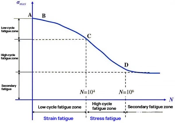
During die service, microfatigue cracks form under repeated alternating stress, gradually expanding and potentially leading to sudden catastrophic failure through fatigue fracture.
(1) Metallurgical defects in raw materials significantly impact fatigue resistance:
(2) Heat treatment issues affecting fatigue performance include:
These factors can lead to a marked reduction in the material’s overall fatigue strength.
(3) Surface quality plays a critical role in fatigue resistance:
Preventive measures:
(1) Strictly select materials, ensure the materials, and control the content of Pb, As, Sn and other low melting point impurities and S, P non-metallic impurities not exceeding the standard;
(2) Material inspection shall be carried out before production, and unqualified raw materials shall not be put into production;
(3) The electroslag remelting refined steel with high purity, less impurities, uniform chemical composition, fine grains, small carbides, good isotropic properties, and high fatigue strength shall be selected to strengthen the surface of the die surface by shot peening and surface chemical infiltration, so that the metal surface is pre pressed to offset the tensile stress generated when the die is in service, and improve the fatigue strength of the die surface;
(4) Improve the machining accuracy and finish of the die surface;
(5) Improve the structure and properties of the chemical layer and hardened layer, and use microcomputer to control the thickness, concentration and hardened layer thickness of the chemical layer.
This crack often occurs during use.
The metal mold cracks due to the chemical reaction or electrochemical reaction process, which causes damage and corrosion of the structure from the surface to the inside.
This is called stress corrosion cracking.
The corrosion resistance of die steel is different due to different structures after heat treatment.
The most corrosion resistant structure is austenite (A), and the most easily corroded structure is troostite (T), which is in turn ferrite (F) – martensite (M) – pearlite (P) – sorbite (S).
Therefore, T structure is not suitable for heat treatment of die steel.
Although the quenched steel has been tempered, due to insufficient tempering, the internal stress in quenching still exists more or less.
When the mold is in service, new stress will be generated under the action of external force.
Stress corrosion cracks will occur whenever there is stress in the metal mold.
Preventive measures:
(1) After quenching, the die steel shall be tempered timely, fully and repeatedly to eliminate the internal stress of quenching;
(2) Generally, it is not suitable to temper the die steel at 350-400 ℃ after quenching.
Because T structure often occurs at this temperature, the die with T structure should be reprocessed, and the die should be treated with rust prevention to improve the corrosion resistance;
(3) The hot working die shall be preheated at low temperature before service, and the cold working die shall be tempered at low temperature to eliminate stress after a stage of service, which can not only prevent and avoid the occurrence of stress corrosion cracks, but also greatly improve the service life of the die, kill two birds with one stone, and can achieve significant technical and economic benefits.

