Why do perfectly planned metal bends sometimes fail? Defects like cracks, warping, and twisting can plague bent parts, compromising their quality and functionality. This article dives into the causes behind these issues, from tensile stress to die rigidity problems, and provides actionable solutions to ensure your bent parts meet the highest standards. Learn how to troubleshoot and prevent these common defects, enhancing the reliability and precision of your metalworking projects.
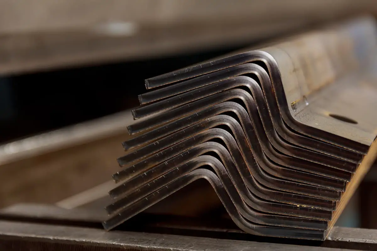
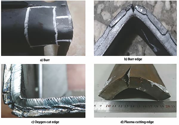
These often form on the exterior edges of the bending deformation zone due to tensile stress. To combat bending cracks, the following measures can be adopted:

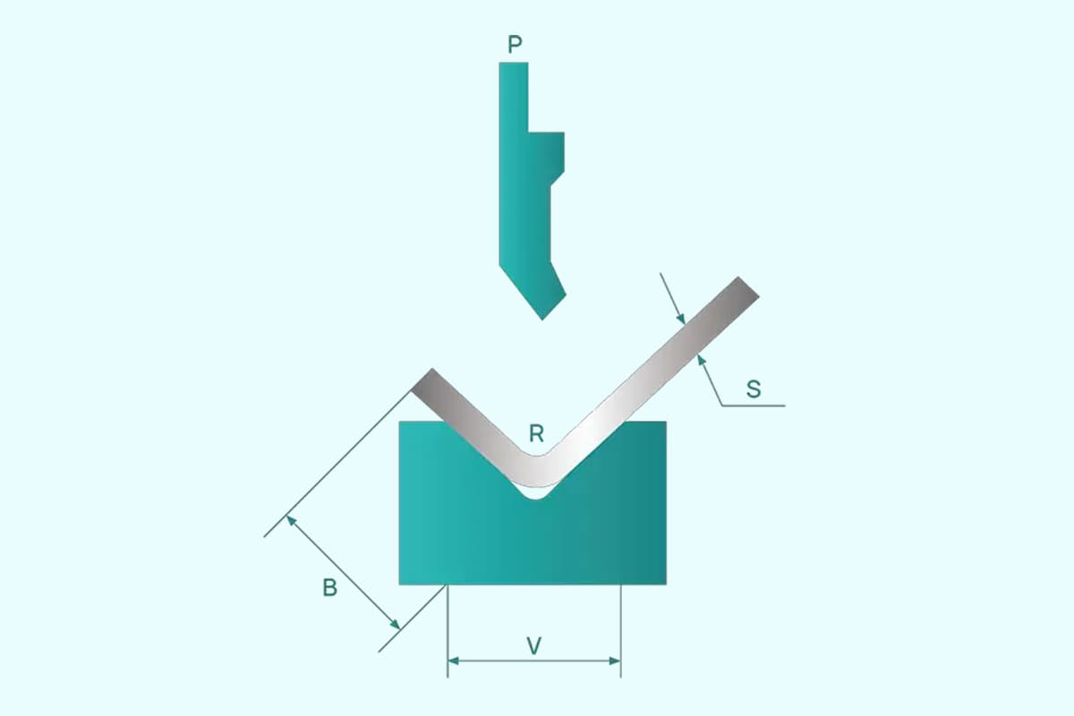
1) Increase the relative bending radius (1r/t), that is, use a larger bending radius during the forming process, add reshaping procedures, and finally make the size of r meet drawing requirements.
2) Enhance the quality of sheet metal blanking to reduce stress concentration caused by burrs.
3) Minimize deformation resistance factors such as tool fillet wear, overly small clearances, poor lubrication, serious thickness discrepancies, and poor plate surface quality.
4) Pay attention to the bending direction and material fiber direction.
5) Increase process notches and process holes. If sharp internal corners exist on the blank outline and need to be bent at this point, the stress concentration can lead to tearing. Therefore, it’s necessary to add process notches or process holes at the transitional corner, or make the bending deformation area far away from the transitional corner.
This is common in wide plate bending and is associated with springback. If the width-wise cross-section is fan-shaped due to deformation, wide plate bending differs because the large width dimension increases deformation resistance.
After bending, the width-wise cross-section hardly deforms, but additional stress emerges within the material along the width direction. After the bending force is removed, this additional stress disappears, causing deformation in the opposite direction of the additional stress.
Thus, width-wise warping occurs. To eliminate warping, the die line of the punch should be made into an arc in advance. This will generate deformation in the opposite direction to the warping during bending. After springback, the warping is compensated and disappears.
This refers to the twisting of a bent component along the width direction such that the projections of the two ends do not coincide. The cause of twisting is due to the blanking force not being in the same plane, which creates a torque that twists the bent component. Another cause of twisting is insufficient die rigidity.
To prevent twisting deformation, either adjust the blanking force to be in the same plane or increase die rigidity.
This refers to a displacement of the blank during bending deformation, causing the bent edge to deviate from its predetermined position and resulting in a scrapped workpiece. Offset is a common quality issue in bending operations, second only to springback. It often occurs on asymmetrical workpieces.
When asymmetrical blanks are bent, the areas of the blank on either side of the bending line are unequal, resulting in varying friction forces at the die clearance and fillet. The side with a smaller friction force enters the die first, causing the workpiece to shift and the dimensions of the two straight edges to not meet drawing requirements.
Offset prevention methods include strategizing on the blank’s positioning and clamping, such as using the final positioning of the process hole based on the initial positioning of the contour; increasing the pressure plate (rod); or using a pressure rod with a notch for both positioning and clamping. For some asymmetrical bent pieces, they can be transformed into symmetrical bending by using a single bending mold to form two asymmetrical pieces, which are then cut into two bent pieces after forming.
In production practice, bent components often fail to meet product drawing requirements due to defects. Common defects in bent component processing and their remedial measures are shown in Table 1.
Table 1: Common Defects in Bent Component Processing and their Remedial Measures.
| Defect | Defect Schematic | Cause of Occurrence | Corrective Measures |
| Surface abrasions |  | 1) The clearance between the punch and die is too small. 2) The fillet radius at the bottom of the die is too minimal. 3) Iron filings and other particulates are adhering to the surface of the bent component. | 1) Appropriately reduce the surface roughness of the convex and concave dies 2) Slightly enlarge the round corner of the concave die 3) Apply a reasonable clearance value and thoroughly clean the surface of the bent part |
| Cracks |  | 1) The bending radius (punch radius r) is too small (less than the minimum lateral bending radius of the sheet metal). 2) The burr side of the sheet metal is situated at the external fillet of the bend. 3) The material exhibits low plasticity. 4) The cold work hardening layer is excessively thick. | 1) Increase the bending radius of the punch die appropriately, so that it is larger than the minimum bending radius of the sheet metal. 2) Place the side of the sheet metal with burrs at the inner corner of the bend. 3) Use materials that have undergone annealing or have good plasticity. 4) Adjust so that the bending line is either perpendicular or at a 45-degree angle to the direction of the sheet metal’s grain. |
| Deflection |  | Induced by the rebound, or during bending, additional stress is generated along the width direction. This stress, on the outer side of the neutral layer, is tensile, while on the inner side, it’s compressive. Once the bending force is removed, the additional stress disappears, causing deformation in the direction opposite to the additional stress, specifically, shortening on the outer side and elongating on the inner side, resulting in bending deformation along the width. | By employing corrective bending and pre-forming the die edge into a curve, deformation in the opposite direction of the bending is induced in the part during bending. Upon recoil, the twisting deformation gets compensated for and disappears. |
| Uneven base |  | The bending die lacks a hold-down (pressure pad) plate, or insufficient hold-down force, causing the sheet metal to not press tightly against the bottom of the punch during bending, resulting in production issues. | Implement a bending mold with a top feeding (or pressing) plate, or appropriately increase the force of the top feeding (or pressing) plate in the bending mold. This ensures that sufficient pressure is applied to the sheet metal at the start of the bending process, guaranteeing a flat bottom in the bent part. |
| Hole distortion |  | The distance from the hole wall to the bending edge is too small (less than the minimum distance from the hole wall to the bending edge), causing the hole to be in or too close to the deformation zone. During bending, the outer side of the neutral layer is stretched, and the inner side is compressed, altering the shape of the hole. | Ensure the distance from the hole edge to the bending side is greater than the minimum distance from the hole edge to the bending side, or process the hole after bending. When the functionality of the bent part permits, a process hole or slot can also be created in the bending area to reduce deformation stress. |
| Changes in the bend angle |  | During bending, both plastic and elastic deformations occur in the metal piece. After the bending force is removed, the elastic deformation disappears immediately, while the plastic deformation remains (known as springback), resulting in the processed metal piece having a shape and size inconsistent with that of the bending mold. | 1) The rebound value, whether precalculated or obtained experimentally, can be compensated or deducted in the corresponding shape and size of the mold’s working portion. This method allows the bend to obtain the shape and size required by the product design. 2) Instead of free bending, corrective bending is employed. |
| Non-parallel bending line and folding edge |  | Bent components with beveled edges located within the deformation zone cannot achieve the desired shape and angle if the straight-edge height is less than twice the minimum bending straight-edge height. | 1) When the use of the bent component permits, the part’s shape should be altered, increasing the dimension of the sloped edge. 2) If the functionality of the bent component doesn’t allow for it, the slope should be processed after bending. |
| U-shaped part with unequal side hole pressure bending |  | 1) Inaccuracy in sheet metal positioning during bending, or slippage during the bending process, results in misalignment of hole centers along the height direction. 2) Due to the rebound effect, the bending angle of both sides is not fully achieved, causing the hole centerlines to be misaligned. Related reading: V & U-shaped Bend Force Calculator | 1) Consider adding positioning process holes when the functionality of the bent part allows. 2) Augment the bending mold with a pressure plate and anti-slip positioning pin. 3) Compensate (or deduct) for the springback value in the corresponding shapes and sizes of the mold working parts. |
| End protrusion |  | This phenomenon is particularly noticeable when bending thick plates. During the bending process, the longitudinal fibers inside the neutral layer are compressed due to compressive stress, and the width direction is stretched due to tensile stress. This results in a protrusion at the ends in the width direction of the bent part. | 1) Position the burr edge of the sheet material on the inside of the bend. 2) Preset process notches at both ends of the blank bending line, and apply negative compensation for stretching in the width direction. |
| Dimensional deviation |  | The asymmetrical shape of the bent component, along with uneven frictional forces, results in an imbalance of stress on both sides of the blank. This leads to the formation of sliding surfaces on the blank during bending, causing discrepancies in dimensions. | 1) Use a bending mold with a top feed (or pressure feed) plate, and incorporate positioning pins for precise plate positioning. 2) When conditions permit, employ symmetric bending followed by part sectioning as the final step. |

