Why do CNC press brake rams deform, causing costly production delays? This article explores the common causes of ram deformation in CNC press brakes, from prolonged usage to material stresses, and provides detailed solutions for prevention and repair. Readers will learn practical methods to mitigate deformation, ensuring higher precision and reduced downtime in their metal fabrication processes.
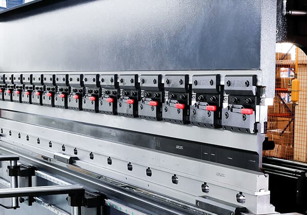
The 640T CNC press brake in the material preparation workshop was introduced by the company in 2006 and is mainly used for forming and straightening carbon steel and stainless steel products.
It has high frequency usage and is the main production equipment in the workshop. The equipment consists of bed, ram, column, deflection compensation mechanism, worktable, rear material device, safety protection device, hydraulic system and electrical system.
The equipment itself only has one basic movement – the up and down reciprocating motion of the ram (driven by two hydraulic cylinders on both sides).
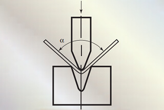
By equipping it with various molds of different shapes, the machine can bend the sheet metal into various shapes and angles.

After prolonged usage, the bottom of the ram body undergoes a certain degree of plastic deformation, resulting in varying degrees of clearance between the upper die fixture and the ram, as well as between the upper die mold and the ram.
The clearance at each position can be measured using a plug gauge, and it is found that the maximum clearance is in the middle of the ram, which results in the inability of the fixture contact surface flatness and straightness at the bottom of the ram to meet the fixture installation requirements.
The fixture cannot effectively clamp the mold, which ultimately leads to slight displacement of the mold during the pressing process, resulting in large forming errors in the processed sheet metal.
This not only makes subsequent assembly impossible but also causes significant waste of human and material resources due to rework and repair.
Operators usually fill the gaps with thin copper sheets of different thicknesses at positions where the clearance is large to temporarily eliminate the movement clearance.
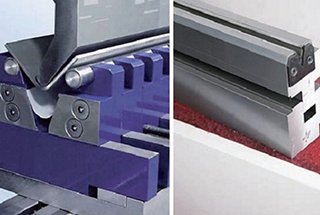
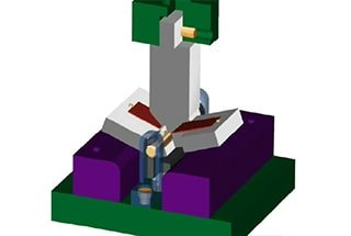
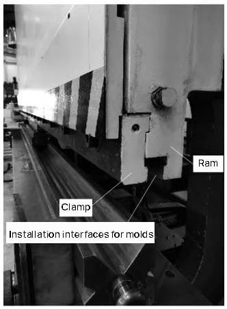
However, this creates a certain equipment hazard, which may not only exacerbate ram wear but also affect the performance of fixtures and molds. The interface of the CNC press brake ram is shown in Figure 1.
press brake ram block is the largest, most complex part of a press brake in terms of both stress and structure. Usually made of welded Q235 steel, the ram block is subjected to a downward bending force on both sides during bending, which is applied by oil cylinders, and connected to the ball block and piston rod.
On the back of the ram block, there are pressure blocks and guide blocks to provide planar constraints for the up-and-down movement of the ram block. The workbench and oil cylinder of the press brake are the main load-bearing parts. The center of the workbench and the center of the oil cylinder are in the same plane.
According to the principle of action and reaction, the force is applied to the contact surface between the ram block and the oil cylinder, which is distributed uniformly and vertically downward.
When the ram block is working, the reactive force of the plate against the ram block acts on the bottom of the ram block, distributed uniformly and vertically upward.
Using ANSYS finite element analysis software to simulate the entire press brake, a corresponding finite element model is established. The deformation of the ram block is symmetrically distributed, and the maximum deformation occurs at the middle position of the bottom of the ram block. The deformation gradually decreases from the middle to both sides.
The researchers verified the deformation of the ram block by using displacement sensors for deformation measurement. They found that the ram block is subjected to horizontal thrust force from the plate while mainly bearing vertical bending force, which shows a trend of being large in the middle and small at both ends.
This result demonstrates the actual deformation trend on site and conforms to the phenomenon of ram block deformation.
Due to the high cost of replacing the entire ram block, which can cost hundreds of thousands of yuan, and the long processing cycle, it is difficult to meet the needs of production sites in a timely manner.
In order to deal with the problem of ram block deformation and to reduce costs and improve stability, among other factors, it is possible to consider machining the clamping surface of the ram block fixture.
After many trials and considerations, three optimized renovation plans have been proposed.
This solution involves disassembling the entire ram and using a high-precision gantry planer to precision-machine the original fixture installation interface. During machining, the reference plane should be selected carefully.
First, the actual deformation degree of each contact surface of the ram installation interface is measured using a dial gauge.
Then, the ram is machined according to the deformation situation.
After machining, it needs to be left for a period of time to ensure stress release and guarantee that the flatness can be controlled within 0.1 mm. If there are higher requirements for roughness, grinding on the grinder is required.
In addition, during processing, the depth of the fixture mounting groove and the width of the mold mounting groove should be ensured to avoid the fixture being unable to install or the mold cannot be clamped due to uneven processing.
Although this scheme has lower maintenance costs and shorter processing cycles, and can ensure short-term use, the overall thickness of the fixture mounting interface becomes thinner, which reduces its strength.
Moreover, during bending, the working center will shift towards the inner side of the throat along the axial direction, and the torque formed will accelerate the deformation of the ram interface. Its service life cannot compare with that of the original size interface.
This solution is suitable for situations where equipment needs to be restored to production in a short period and also retains the possibility of further improvement. The processing is illustrated in Figure 2.

This solution involves completely removing the original fixture installation interface and machining a new one on the ram according to the standard size of the equipment when it was first produced. This solution has relatively low maintenance costs and no additional material costs.
However, because the installation interface needs to be cut off entirely, the interface position needs to be moved up by almost 120 mm as calculated on site.
According to the limit of this model of press brake, the ram can only continue to descend by 90 mm along the vertical direction before the cylinder reaches its lower limit position, and the working stroke of the cylinder cannot meet the requirements.
Furthermore, if the option of raising the entire lower working table of the press brake (including but not limited to increasing the thickness of the table) is considered to address the insufficient cylinder stroke issue, it will also lead to the need to lift the rear mold lifting shaft synchronously in order to position the workpiece.
In this situation, the screw stroke of the lifting shaft is also limited, so this modification solution is not suitable for this model of press brake.
This solution involves cutting off the original fixture installation interface and producing a set of transition blocks according to the equipment’s standard dimensions to connect the fixture and the ram block.
The transition block is connected to the original ram block using high-strength bolts, and installation holes are evenly distributed on the transition block at intervals of 500 mm.
In addition, a transverse centerline position with a keyway is provided for longitudinal positioning to ensure high-precision positioning standards (under this working condition, there is no need for the key to transmit torque and large loads, so it is difficult for the key to wear out or fail).
To meet the load-bearing capacity requirement of not less than 142 t/m and improve the strength and wear resistance of the ram block interface, the material selection was reconsidered.
After comparative research, it was found that the ultra-high-strength steel material 42CrMo is suitable for the production of transition blocks for press brakes.
The mechanical properties of the original ram block material and the new transition block material are compared in Table 1, and the material has greatly improved mechanical performance.
Table 1 – Mechanical Performance Comparison of ram block Materials
| Material types | Tensile strength σb/MPa | Yield strength σs/MPa |
| Q235A | 370-500 | 180-250 |
| 42CrMo | ≥1080 | ≥930 |
The advantages of this solution are that it retains the original structural design, has high reliability, and the transition block can be directly processed and manufactured according to the drawings. The processing accuracy is easy to test and control, and the produced transition block has high precision.
At the same time, the transition block made from this material is difficult to undergo plastic deformation, greatly extending its service life.
However, the downside is that during processing, the transition block needs to be drilled and keyed to match the ram block, which requires a longer processing cycle compared to directly processing on the original ram block and is relatively more costly.
The installation effect of the transition block is shown in Figure 3.

Through the study of the deformation problem of the 640T press brake ram block, not only is there guidance for handling subsequent ram block deformation problems, but different processing solutions can be selected for different types of CNC press brakes or under different requirements.
The straightness and planarity of the processed ram block can meet accuracy requirements, and the produced products meet process requirements. It is also beneficial to improve the safety and reliability of the equipment.

