Convex Mold Design for Continuous Precision Stamping
Imagine a world where precision and efficiency in manufacturing are paramount. How do engineers ensure that every stamped part meets exacting standards without skyrocketing costs? This article delves into the intricacies of convex mold design for continuous precision stamping. You’ll uncover the key principles behind creating durable, cost-effective molds that streamline production processes. From understanding structural types to choosing the right materials, this guide provides the essential knowledge to enhance mold performance and longevity. Discover how strategic design choices can revolutionize your stamping operations.
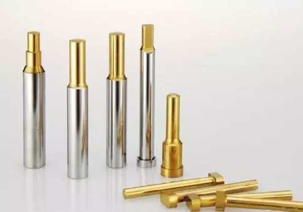
The punch is one of the most important components in stamping dies, which includes various indicators such as structure, installation, processing, material, and cost in its design.
Designing the punch correctly, effectively, reasonably, and economically can not only improve the service life of the die, reduce manufacturing costs, and increase production capacity, but also facilitate processing and maintenance, making subsequent stamping production efficient and smooth.
Die is known as the mother of industry, and it is the basis for ensuring manufacturing accuracy and quality. Germany and Japan have very high evaluations of the role and importance of dies in industry and economy.
In 2002, due to the inadequate technology of a European supplier of computer connector terminal molds, Intel produced unqualified parts, allowing a Taiwanese-funded enterprise in Shenzhen to use 11 high-speed punch presses to produce the terminal day and night for several months, with a monthly output value exceeding NT$1 billion. This was a miracle for a manufacturing factory with more than 3,000 employees.
Today, the application of continuous precision stamping dies in modern part production is increasing, and its importance is becoming more prominent. Precision stamping of thin materials is a necessary process for producing modern electronic parts, and its punch design is particularly important.
Design of the Punch
1. Structure types of punches
The structure of punches can be divided into two types: insert and integral. The insert type combines multiple small punches together, but its assembly error is relatively large and inconvenient for maintenance, so it is less used in modern high-speed stamping dies.
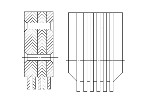
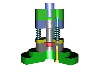
Figure 1: Inserted Punch Die
The integral punch has four main structure types:
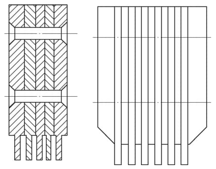
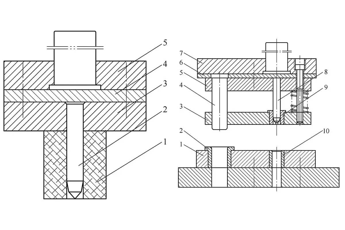
Shoulder-type punch (see Figure 2):
Figure 2: Shoulder Type Punch Die
It was widely used in the past, with a large size of the cutting edge and a straight-through type in the lower part. The shoulder is designed to prevent the punch from being pulled out of the fixed plate during unloading. The shoulder is designed asymmetrically to avoid installation errors.
However, the shoulder makes disassembling and maintenance inconvenient, as the punch can only be taken out by disassembling the mold, which would seriously affect the precision of the mold.
Straight-through punch (see Figure 3):
Figure 3: Straight-Through Punch Die
This type of punch has a large cutting edge size and is an improvement of the shoulder-type punch. It no longer has a shoulder part, and the cutting edge has the same shape and size as the fixed part. This improvement increases the application rate of straight-through punches.
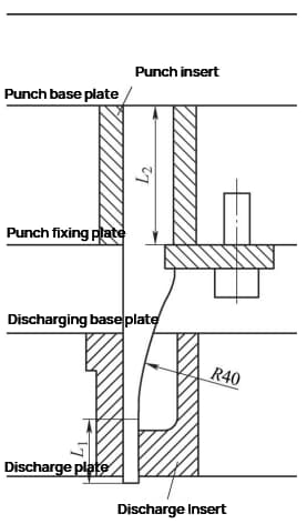
Reinforced punch (see Figure 4):
Figure 4: Reinforced Punch Die
With the increasing precision of modern die production, the size of the cutting edge in the lower part becomes smaller, and the rigidity and strength of the straight-through punch are weak. In the past, punch sleeves were often added.
To improve the rigidity and strength of the punch, a straight-through section L1 (6-10mm) is designed in the lower part, and the middle is reinforced with an R40mm arc (the minimum radius of the optical grinding wheel).
The upper installation part is designed as a rectangle for easy maintenance and shifting. As there is a slot for the pressure plate to prevent misalignment, no additional anti-misalignment structure is needed.
When designing, it is best to place the cutting edge close to the sides of the reinforced punch for easy installation and positioning, reducing processing difficulty and cost. Reinforced punches are currently the most commonly used punch structure.
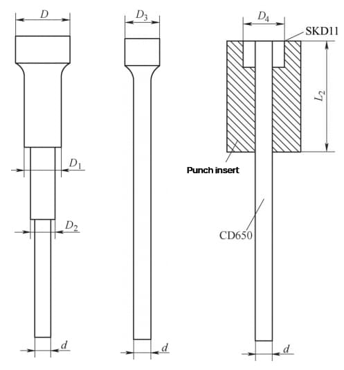
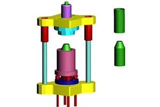
Round punch (see Figure 5):
The round punch is widely used, and almost every die set uses it. When the diameter of the punch is very small, it is difficult to manufacture multi-axis shoulder-type punches and single-axis shoulder-type punches.
The sticky head punch cuts the small diameter punch material (CD650) to the required length and uses an alloy mold steel (SKD11) to make a sleeve outside the installation part.
The two are bonded together with anaerobic adhesive, resulting in the same effect as a single-axis shoulder-type round punch but at a cost of less than 1/3. Since the round punch is not conducive to shifting during maintenance, a rectangular punch insert piece is often designed and placed on the punch.
2. Fixed installation methods of punches
The installation of the punch die is carried out on the punch die fixed plate, which has requirements for both positioning and fixing. The positioning of the punch die is achieved through the combination of the punch die and the holes on the fixed plate.
The fixing can be accomplished by hanging shoulders, bolts, rivets, epoxy resin glue, side pins, horizontal pins, and pressure plates.
For a straight-through punch die, due to its irregular shape, an auxiliary rectangular punch die insert needs to be added to the installation position.
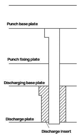
The fixed plate has a certain distance between the fixed position of the punch die and the working position of the punch die edge, which can easily cause the punch die to become unstable and fail.
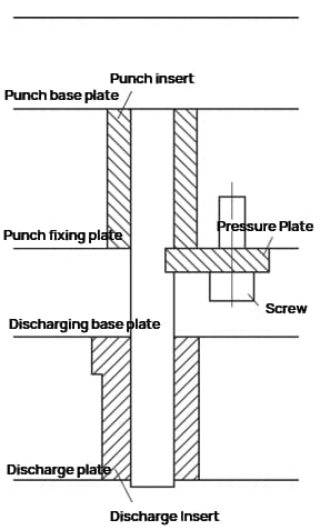
If the size of the punch die edge is small, normal production is impossible. When the punch die is made into a pressure plate for fixing, a discharge insert should be added. When the punch die passes through the discharge insert to perform punching with the die, the discharge insert can guide the punch die into the die to protect the punch die from lateral forces.
The unilateral clearance design between the punch die and the discharge insert is 0.003-0.005mm or even smaller. When the punch die is working, the discharge insert is exposed about 3mm, which is not easily damaged. The size of the punch die installation position is designed to be the same as or slightly smaller than the size of the square hole on the fixed plate.
The pressure plate groove is 0.02-0.05mm lower than the fixed plate, allowing the punch die to have a little room for movement inside the fixed plate. The true positioning relies on the discharge insert, avoiding interference between the fixed plate and the discharge insert.
Since the positioning point of the discharge insert is the working position of the punch die edge, the effect is optimal. Remove the pressure plate screws and pull out the pressure plate to remove the punch die.
The disassembly of the punch die is convenient, enabling quick maintenance and repair of the punch die.
3. Material Selection for Punch Die
The punch die should be able to withstand a certain amount of impact force while also having high wear resistance.
Therefore, a high-hardness material with a certain toughness should be selected. For continuous precision stamping dies, the material selection for the punch die is even more critical to meet their mass production capability.
Traditional punch die materials such as Cr12MoV, Cr12, and SKD11 can only be used to make templates or inserts in continuous precision stamping dies.
The most commonly used material for punch dies in continuous precision stamping dies is foreign tungsten steel material CD650, which has a high surface quality, is extremely wear-resistant, and has a maximum hardness of 90HRA.
The second most commonly used material is foreign high-chromium molybdenum vanadium powder material ASP-23, with the best hardness at around 63HRC.
4. Processing Methods for Punch Die
The irregular shape of straight-through punch dies is usually processed using slow wire cutting, with one cut and one or two repairs.
Although slow wire cutting has high processing accuracy, the thin oxide layer generated on the surface at high temperatures can also affect it, resulting in a dimensional accuracy of ±0.003mm.
Hanging shoulder punch dies are processed using a regular small surface grinding machine (G), and attention should be paid to designing the hanging shoulder in a location that does not affect processing.
Reinforced punch dies are processed using an optical grinding machine (PG), which is more expensive. The latter two processing methods can achieve a dimensional accuracy of ±0.002mm.
Conclusion
Continuous precision stamping dies have high requirements for die life. The lifespan of electronic and communication small hardware stamping dies typically needs to reach 100kk (100 million) strokes, while the lifespan of terminal dies needs to reach 500kk (500 million) strokes.
When designing the punch die, various factors such as product precision, production goals, die life, processing difficulty, ease of maintenance, and economic performance should be considered comprehensively.
By designing the punch die correctly, reasonably, and flexibly according to the actual situation, it can meet product quality requirements, facilitate timely improvements, and ensure smooth production.
As the founder of MachineMFG, I have dedicated over a decade of my career to the metalworking industry. My extensive experience has allowed me to become an expert in the fields of sheet metal fabrication, machining, mechanical engineering, and machine tools for metals. I am constantly thinking, reading, and writing about these subjects, constantly striving to stay at the forefront of my field. Let my knowledge and expertise be an asset to your business.
Imagine extending the lifespan of your molds significantly—what impact would that have on your production efficiency and costs? This article explores 12 innovative technical measures to improve mold life, from…
Why do molds deform during heat treatment, causing costly defects? This article delves into the root causes, such as material selection, mold design, and manufacturing processes, and outlines preventive measures.…
Have you ever wondered what makes a punch design critical for stamping dies? This article breaks down the essential principles behind punch structures, from circular and non-circular shapes to the…
What makes stamping dies last longer? This blog explores the key factors that influence the longevity of cold stamping dies, including material selection, heat treatment, and maintenance practices. Learn how…
Ever wondered how everyday objects are shaped with precision? This article explores the fascinating world of joint construction stamping technology. You'll learn about the process, from obtaining technical drawings to…
Intrigued by the marvels of metal stamping? In this blog post, we dive into the fascinating world of hole flanging, necking, and bulging. Our expert mechanical engineer will guide you…
Have you ever wondered how a flat sheet of metal can be transformed into a complex, hollow part? Deep drawing, a fascinating forming process, makes this possible. In this article,…
Have you ever wondered how intricate metal parts are made with precision? This article explores the fascinating world of thread tapping and flanging dies, revealing the secrets behind their design…
Wrinkling in metal stamping can undermine the quality of stamped parts, but it can be controlled through specific practices. This article explores factors like stretch depth, blank holder force, and…