How can engineers ensure their liquid cooling systems perform efficiently while minimizing maintenance issues? This article explores key design principles for liquid cooling system piping, from selecting appropriate materials and pipe diameters to ensuring proper installation methods. Readers will gain insights into optimizing system performance, extending equipment lifespan, and avoiding common pitfalls in cooling system design.
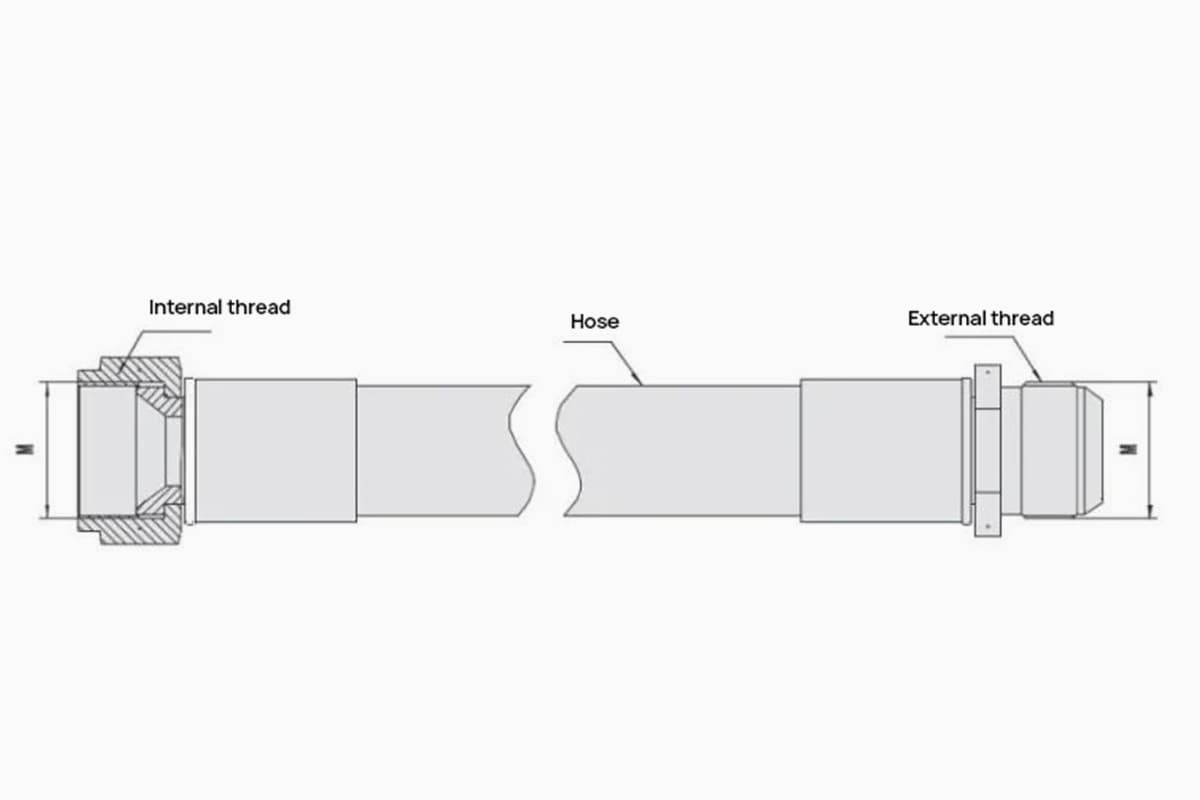
Liquid cooling pipelines primarily serve to establish connections between the liquid cooling source and the equipment, from one piece of equipment to another, and between equipment and other pipelines, utilizing flexible (rigid) hose connections. These pipelines come in two types: flexible hoses and metal pipes.
Interface Examples

One end of the pipeline features an internal thread, while the other end showcases an external thread. Both ends utilize a 74° conical sealing method.
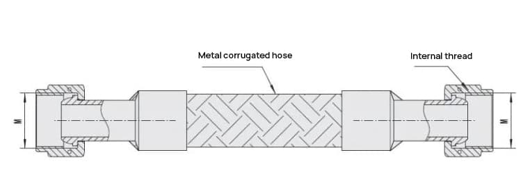
Both ends of the pipeline have internal threads, employing a 60° spherical joint seal.
External threads: Metric, British threads, and pipe threads. Sealing methods include 74°, 60°, 24° conical seals, and other sealing techniques.
Internal threads: Metric, British threads, and pipe threads. Sealing methods include 74°, 60°, 24° conical seals, and other sealing techniques.
Barbed Pagoda Joints: The outer circular dimension of the barb is tailored according to the user’s pipeline.
Flange: Square plate structure; standard sleeve flanges, standard flanges, etc.
Instructions for Choosing a Liquid Cooling Pipeline
Liquid cooling pipelines are primarily used to establish connections between the liquid cooling source and the equipment, from one piece of equipment to another, and between equipment and other pipelines, utilizing flexible (rigid) hose connections.
The selection of the pipeline affects its lifespan, reliability, maintainability, and other performance characteristics. The following factors should be considered when making a selection:
1. Maximum Working Pressure:
The maximum working pressure of the pipeline should not exceed the maximum working pressure value of the specific pipeline specification (a certain margin should be reserved).
2. Operating Temperature:
Choose based on the actual environmental temperature and operating temperature of the pipeline. The operating temperature range should be within the applicable temperature range of the specific pipeline specification.
3. Pipeline Diameter:
Select based on the flow rate and velocity size matched by the system.
4. Pipeline Joint Method:
Choose according to the user’s actual usage situation.
5. Fluid Medium:
Please refer to the sample.
6. Fixation:
For flexible hoses used in vibrating environments, it is recommended to fix them at intervals of 250mm to 400mm according to the pipe diameter size. Depending on the actual situation, standard clamps or tie wraps can be used for fixation.
1) Ensure the delivery of the necessary refrigerant liquid to the evaporator, thereby guaranteeing cooling capacity;
2) Ensure the refrigerant flows through the system with the minimum pressure drop, to avoid additional power loss;
3) Ensure the refrigerant and cooling oil return to the compressor as much as possible without accumulating in the pipeline, thereby guaranteeing the normal operation of the compressor;
4) Prevent the refrigerant liquid and cooling oil from causing impact damage to the compressor;
5) Ensure reasonable costs for both the pipeline and refrigerant.

When choosing the pipe diameter, different considerations apply for refrigeration systems with different purposes. For comfort air conditioning, which is typically used for about 8-18 hours per day, initial investment matters.
If you aim to minimize pressure drop by excessively increasing pipe diameter, the cost for both the piping and refrigerant charging will rise. Therefore, a solution with a lower cost can be chosen, provided that it ensures sufficient oil return and a reasonable pressure drop.
For industrial air conditioning, particularly in server rooms that operate round-the-clock, operating costs are more of a concern. In this case, a solution ensuring high refrigeration efficiency during oil return can be considered.
The two most significant factors affecting the choice of pipe diameter are:
01) Piping pressure drop
02) Piping flow velocity
For a given refrigeration system, an increase in pressure drop means a decrease in refrigerant flow, which will reduce the refrigeration capacity. To increase refrigeration capacity, the refrigerant charge must be increased to maintain the original refrigerant flow and thus the original refrigeration capacity.
However, to overcome the increased pressure drop, the compressor power will have to be increased. Our company has provided some reference values, which show that the suction pipe pressure drop has a greater impact on the system than the exhaust pipe pressure drop.
| Pressure Drop, F | Pipe Sections | Cooling Capacity % | HP/Ton% |
| 0 | / | 100 | 100 |
| 2 | Intake Pipe | 95.7 | 103.5 |
| 2 | Exhaust Pipe | 98.4 | 103.5 |
| 4 | Intake Pipe | 92.2 | 106.8 |
| 4 | Exhaust Pipe | 96.8 | 106.8 |
The flow rate is related to both the pressure drop and the oil return. The refrigerant oil in the refrigeration system performs the following functions:
1. Lubricates moving parts;
2. Cools the compressor;
3. Acts as a seal;
4. Powers the unloading mechanism;
5. Removes impurities and cleans parts.
Moreover, if the refrigerant oil accumulates in the heat exchange tubes of the heat exchanger, it will reduce the heat exchange capacity of the exchanger. Therefore, the refrigerant oil flowing out with the refrigerant should be returned to the compressor as much as possible, otherwise, it will cause the compressor to run out of oil.
The refrigerant oil and the refrigerant liquid have a certain solubility, so they can easily flow together in the pipeline. However, the solubility with the refrigerant gas is relatively poor, so the refrigerant gas needs to reach a certain speed to drive the flow of the refrigerant oil.
The factor affecting the flow rate of the refrigerant is the diameter of the pipe. The smaller the diameter, the faster the refrigerant speed, and the inevitable increase in pressure drop. Therefore, the pressure drop and oil return are a contradiction.
To return oil smoothly, the refrigerant speed needs to be fast. If the refrigerant speed is fast, the pressure drop is large. Therefore, a balance point must be found and an appropriate pipe diameter selected.
We will first introduce our company’s method of selecting pipe diameter based on the flow rate curve. Below are the reference values for the flow rate of each section of the pipeline.
Reference values for flow velocity in each pipe segment.
| Pipe Segment | ASHRAE Recommended Speed (fpm) | Speed (m/s) | Limit Value (fpm) | Speed (m/s) |
| Intake Pipe | 900-4000 | 4.6-20.3 | 2300(The noise will be significantly louder beyond this point.) | 12 |
| Exhaust Pipe | 2000-3500 | 10.2-17.8 | 500/H,1000/V | 2.5-20.3 |
| Condenser to Storage Tank | <100 | <0.5 | ||
| Storage Tank to Expansion Valve | 125-450 | 0.6-2.3 | 400(YORK) | 2.0 |
| Horizontal Section | 750 | 3.8 | 700 | 3.56 |
| Rising Section | 1500 | 7.6 | 1000 (YORK) | 5.08 |
Due to various sources of information, some reference values might be inconsistent. Here, I’ll try to provide considerations and sources for your reference, and you can choose accordingly during usage.
The method of selecting pipe diameters using flow rate curves first requires knowledge of the cooling capacity and temperatures in each pipe section (exhaust pipe, suction pipe, liquid pipe). Then, based on the range of the table above and the characteristics of the product’s purpose, determine the pipe diameter.
01) Exhaust pipe:
Although the pressure drop in the exhaust pipe does not have as substantial an impact on the cooling capacity as the suction pipe, it can increase power consumption. Hence, for R22, the maximum value should not exceed 6psi (0.4bar).
02) Condenser to liquid storage pipe:
To allow the liquid to flow out of the condenser promptly after condensation and not occupy the heat exchange area of the condenser, this section requires a larger pipe diameter. This prevents congestion of the liquid refrigerant and ensures that the liquid can flow out of the condenser in time, thus reducing the condensing area.
03) Liquid storage to expansion valve connection pipe:
The most critical consideration for this section is to avoid flash evaporation due to pressure drops, especially for rising pipelines. For example, with R22, for every meter rise, there is a 0.115bar pressure loss. With every 0.38bar pressure loss, the saturation temperature drops by 1°C.
Consequently, if the degree of subcooling also drops by 1°C, and if the pipeline rises by 10 meters, leading to a pressure loss of 1.115bar, the refrigerant’s saturation temperature drops approximately 3°C. Ignoring other pressure losses, the refrigerant liquid’s degree of subcooling also drops by 3°C. This implies that the minimum degree of subcooling should be greater than 3°C to prevent the refrigerant liquid from flash evaporating.
The table below shows the change in pressure when the liquid’s saturation temperature changes by about 0.5°C (1°F) at a condensing temperature of 38°C (100°F) (1 psi = 0.069 bar).
| Refrigerant | Pressure psi | Pressure bar | Refrigerant | Pressure psi | Pressure bar | Refrigerant | Pressure psi | Pressure bar |
| R22 | 2.8 | 0.19 | R410A | 4.6 | 0.32 | R407C | 3.4 | 0.23 |
| R404A | 3.4 | 0.23 | R134A | 2.1 | 0.14 |
4) Intake Pipe:
This conduit directly determines the air intake of the compressor and thus significantly impacts the system. If there’s a substantial pressure drop, the specific volume of the refrigerant increases, thereby reducing the mass of the same volume.
This, in turn, decreases the mass flow rate of the refrigerant drawn into the compressor, ultimately diminishing the cooling capacity. According to sources, for every 1 psi loss in pressure, the cooling capacity of R22 drops by 1%, while for R410A, it decreases by 0.6%.
| The variation in saturation pressure when the intake pipe’s saturation temperature changes by 2°F (1°C). | ||||||
| Evaporation Temperature F/C | R22 psig | R22bar | R407Cpsig | R407Cbar | R410Apsig | R410Abar |
| 45/7.2 | 3.0 | 0.20 | 3.1 | 0.21 | 5.0 | 0.34 |
| 20/-6.7 | 2.2 | 0.15 | 2.1 | 0.14 | 3.0 | 0.2 |
| 0/-17.8 | 1.7 | 0.12 | 1.6 | 0.11 | 2.6 | 0.18 |
| -20/-28.9 | 1.2 | 0.08 | 1.1 | 0.08 | 1.9 | 0.13 |
| -40/-40 | 0.8 | 0.06 | 0.7 | 0.05 | 1.3 | 0.09 |
| Evaporation Temperature F/C | R134apsig | R134abar | R404Apsig | R404Abar | ||
| 45/7.2 | 2.0 | 0.14 | 3.7 | 0.26 | ||
| 20/-6.7 | 1.4 | 0.10 | 2.7 | 0.19 | ||
| 0/-17.8 | 1.0 | 0.07 | 2.0 | 0.14 | ||
| -20/-28.9 | 0.75 | 0.05 | 1.4 | 0.10 | ||
| -40/-40 | 0.45 | 0.03 | 1.0 | 0.07 | ||

