1. Main causes of dimensional error of parts caused by flame cutting
The main causes of errors in NC cutting and blanking include thermal deformation of the steel plate, operator technique, flatness of the support platform, equipment accuracy, and the degree of corrosion on the steel plate surface.
2. Dimensional error analysis of parts produced by flame cutting and targeted measures
Flame cutting of steel plates always involves hot deformation. However, the dimensional errors in hot deformation parts can be significantly reduced. The cutting speed and part quality are affected by the operator’s skills.
The flatness of the support platform and the accuracy of the equipment have the greatest impact on the size of the parts. Inaccuracies can often result in parts being scrapped directly. Additionally, the corrosion of the steel plate surface can affect both the cutting quality and cutting speed.
2.1 Dimensional error of parts caused by thermal deformation of steel plate
Thermal deformation in steel plates is mainly noticeable in slender parts. Based on years of cutting practice and analysis, it has been determined that the dimensional errors in parts caused by thermal deformation can be minimized by focusing on the following three aspects:
2.1.1 Drawing part graphics
When creating graphics for parts, make sure to include an appropriate amount of thermal expansion compensation in the length direction of the part. The compensation amount should be selected based on the specific characteristics of each individual part.
Advantages: it directly compensates for the dimensional error of parts caused by thermal expansion;
Disadvantages: it is only applicable to square parts, and other shapes are not easy to compensate for.
2.1.2 Detailed discharge process
Starting from the discharge aspect, refine the discharge process, and formulate a special discharge process for volatile parts.
2.1.2 Use of common edge
Utilizing a common edge can decrease cutting time, minimize heat intake by the steel plate, decrease the expansion of the steel plate, and consequently lessen the dimensional errors of parts.
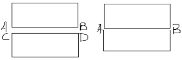
As depicted in Figure 1, when a common edge is not created, AB and CD on two adjoining sides of two parts need to be cut separately.
On the other hand, after utilizing a common edge, only AB edge needs to be cut, and CD edge does not require cutting.
This not only reduces errors in parts but also enhances cutting efficiency and plate utilization.
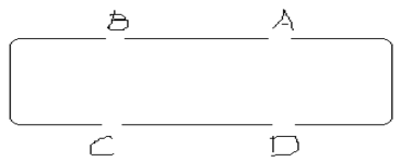
2.1.2 Reasonable cutting direction
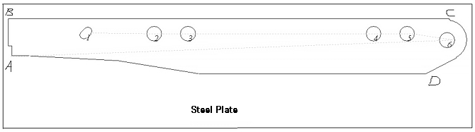
Determine the reasonable cutting direction of the part according to the actual situation, first cut the hole, then cut the shape, and first cut the edge close to the edge of the steel plate.
Try to ensure that there must be sufficient connection stiffness between the part and the steel plate before the part is cut close to the completion point, so as to ensure the cutting size and accuracy of the part.
For example, in Fig. 2, cut the inner hole (1-6) first, and then cut the outer contour in the order of A, B, C, D and A.
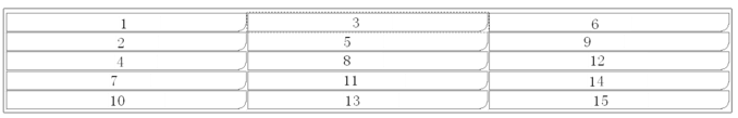
2.1.3 Reasonable part layout and cutting path
The error caused by steel plate deformation can be minimized through appropriate part layout and adjustment of the cutting path.
As illustrated in Figure 3, T-shaped parts that are susceptible to deformation should be paired with smaller parts that are less likely to deform. This helps reduce excessive heating in localized areas, minimizes thermal deformation, and ensures the accuracy of the part dimensions.
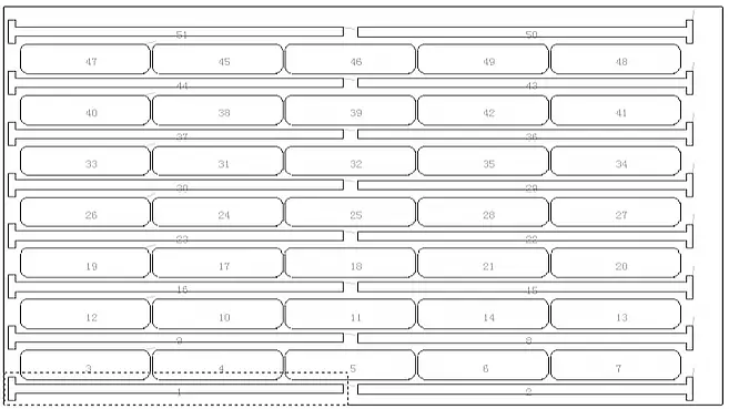
To minimize deformation in slender parts, dislocation cutting should be used when discharging them.
As shown in Figure 4, after cutting part 2, the second column should be used to cut part 3. Once part 2 has been allowed to cool for a certain time, it should be turned over to cut part 4.
Efforts should be made to avoid excessive localized heating of the steel plate, minimize thermal deformation, and ensure the accuracy of the part dimensions as much as possible.
2.1.2 Setting interval
To reduce the error caused by steel plate deformation (as shown in Fig. 5), it is recommended to set intervals. Please note that sections A, B, C, and D should not be cut temporarily but during platform cleaning.
Advantages: directly and effectively reduce part deformation;
Disadvantages: the setting of the interval increases the number of cutting perforations, increases the cutting time, and increases the consumption of the cutting nozzle.
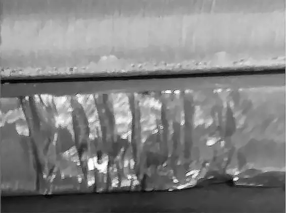
Cutting the gap (as shown in Fig. 6) may result in scars left by the platform cleaning personnel.
Subsequent repair welding and grinding will be necessary.
According to different situations, choosing and using appropriate methods or a combination of several methods to control the deformation of steel plate can play an obvious role.
2.2. Dimensional error of parts caused by NC operator technology
In theory, when using the same equipment and NC program, the parts being cut should be identical. However, in reality, this is not always the case.
Even with the correct procedure, parts cut by different operators may have variations in size and errors, and some may even need to be scrapped.
To ensure that the parts are cut properly, the appropriate cutting nozzle should be chosen based on the thickness of the steel plate. The flame should be adjusted accordingly and the corresponding slit compensation should be set to ensure that the parts are of high quality.
For reference, please see the table below, which provides the gas cutting process parameters.
|
Cutting process parameters
|
|
Cutting nozzle number
|
Cut oxygen hole diameter /mm
|
Cutting thickness
/mm
|
Cutting speed mm / min
|
Preheating time /s
|
Oxygen pressure Mpa
|
Gas pressure Mpa
|
Slit compensation value /mm
|
|
1
|
1.0
|
5-10
|
700-500
|
5-12
|
0.6-0.7
|
>0.03
|
2
|
|
2
|
1.2
|
10-20
|
600-380
|
15-25
|
0.6-0.7
|
>0.03
|
2.5
|
|
3
|
1.4
|
20-40
|
500-350
|
25-30
|
0.6~0.7
|
>0.03
|
3
|
|
4
|
1.6
|
40~60
|
420-300
|
35-50
|
0.6-0.7
|
>0.03
|
3.5
|
|
5
|
1.8
|
60-100
|
320-200
|
50-80
|
0.6-0.7
|
>0.03
|
3.5
|
|
6
|
2.0
|
100-150
|
260~140
|
80-120
|
0.7-0.8
|
>0.04
|
3.5
|
Note: the purity of oxygen is above 99.5%.
2.3. Dimensional error of parts caused by supporting platform
The primary reason for dimensional errors in parts caused by the support platform is due to the support platform’s plane not being parallel to the guide rail surface of the NC cutting machine.
The working platform of the supporting steel plate is frequently impacted and bumped on the loading and unloading platform, leading to its plane becoming uneven and not parallel to the guide rail surface of the NC cutting machine.
If the unevenness is significant, it may cause the cutting torch of the cutting machine to be non-perpendicular to the steel plate, resulting in the inclination of the thickness direction of the entire part.
Due to long-term flame cutting, the insert plate of the support platform may suffer from cutting damage and slag adhesion, leading to the local unevenness of the support platform.
During the part cutting process, the part may become partially suspended, resulting in partial inclination of the part’s thickness direction.
When the steel plate thickness is relatively large, the part size will have a significant error.
2.4. Dimensional error of parts caused by equipment accuracy
The accuracy of the equipment’s guide rail has a direct impact on the accuracy of the cut parts. To minimize errors caused by guide rail accuracy, it is essential to regularly maintain and check the parallelism and flatness of the guide rail.
Protecting equipment parameters is crucial. Any changes made to the vertical and horizontal parameters of the equipment can result in a significant number of parts being scrapped.
Operators must perform thorough self-inspection of parts, especially large ones, and promptly report any problems found. This approach will effectively help in identifying such issues.
3. Conclusion
Various methods can be combined to effectively reduce errors and improve product quality based on the causes of errors in different parts.