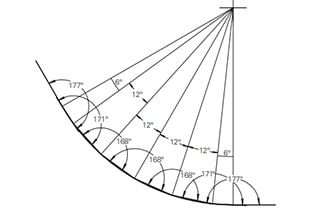
0° – 180° Bend Allowance Chart for Sheet Metal Bending
Have you ever wondered how sheet metal parts are designed and manufactured with precision? In this blog post, we'll dive into the fascinating world of bend allowance - a crucial…
Have you ever wondered how different materials affect sheet metal bending? In this insightful article, a seasoned mechanical engineer shares their expertise on the impact of material types, thickness, and other factors on bending calculations. Discover valuable insights that can help you optimize your sheet metal fabrication processes and achieve precise results. Read on to learn from an industry expert and take your bending knowledge to the next level!
Our comprehensive online sheet metal bending calculator is an essential tool for precision metalworking, enabling you to swiftly and accurately determine critical parameters for sheet metal bending operations. This advanced calculator provides key insights into:
Instructions for Optimal Use:
Leverage this powerful calculator to enhance your sheet metal fabrication process, improve accuracy, reduce material waste, and streamline your production workflow.
Related reading:
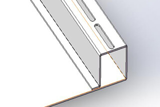
Sheet metal bending is a fundamental process in metal fabrication that involves deforming a sheet of metal along a straight axis. This process is essential for creating a wide range of metal products with varying shapes and functionalities. To achieve precise and accurate bends, several key concepts need to be understood and considered during the design and manufacturing stages.
The bending process begins with a detailed design of the final part. This involves creating 3D models using CAD software such as AutoCAD or SolidWorks. The design must account for various factors, including bend allowance, reliefs, and bend lines. Properly prepared files ensure that the final product meets the desired specifications and quality standards.
Bend allowance represents the length of the neutral axis from the beginning to the end of the bend. The K-factor is a coefficient that helps determine the position of the neutral axis relative to the material thickness. It varies depending on the material properties and bending method used. For example, in a case study involving aluminum sheet metal, a K-factor of 0.3 was used to achieve accurate bends. Understanding and accurately calculating the bend allowance and K-factor are essential for achieving precise bends and maintaining the overall dimensions of the part.
The bend radius is the curvature of the bend and is vital for maintaining the structural integrity of the sheet metal. The minimum bend radius should typically be at least equal to the thickness of the sheet metal to prevent deformation or cracking. Ensuring consistent bend radii across all bends can also contribute to cost-effective and efficient designs.
Springback is the tendency of a bent sheet metal part to partially return to its original shape after the bending force is removed. This phenomenon can lead to inaccuracies in the final part dimensions. To compensate for springback, additional force may be applied through methods like bottoming and coining. Bottoming compresses the sheet metal to the bottom of the die, effectively eliminating springback. Coining involves applying high pressure to create a permanent deformation, further reducing the effects of springback.
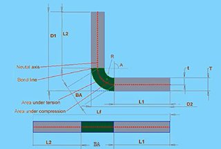
The neutral axis is an imaginary line within the sheet metal that does not experience stretching or compression during bending. The tension zone is located on the outside of the bend where the material stretches, while the compression zone is on the inside where the material compresses. Understanding these zones is crucial for accurate bending calculations and for predicting the behavior of the material during the bending process.
Bend orientation refers to the direction in which bends are made. For cost-effective and efficient production, bends originating from the same plane should be oriented in the same direction. This approach reduces the need to reorient the part, saving time and resources. Consistent bend orientation also helps maintain uniform tooling and setup throughout the manufacturing process.
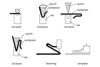
Several bending methods are employed in the industry, each with its own advantages and limitations:
By thoroughly understanding these key concepts, designers and engineers can make informed decisions during the bending process, ensuring high-quality and precise sheet metal parts.
Below are answers to some frequently asked questions:
The K-factor in sheet metal bending is a crucial parameter that represents the ratio of the distance from the neutral axis to the material thickness. The neutral axis is an imaginary line within the metal that experiences no compression or stretching during bending. This position shifts from the midpoint of the material thickness as the metal is bent.
Determining the K-factor involves both measurement and calculation. Typically, you bend sample pieces of the metal and measure key dimensions, including the inside radius of the bend, the material thickness, and the bend allowance. The K-factor can be calculated using the formula:
The complementary bend angle is (180°- included angle)
For convenience, K-factor charts and tables are often used. These provide typical values based on material type, thickness, and bending method. The K-factor is influenced by various factors, including material properties, bending radius, material thickness, and the bending method used.
K-factor values generally range between 0.3 and 0.5. For instance, soft materials like soft copper have a K-factor around 0.35, semi-hard materials like mild steel and aluminum around 0.41, and hard materials like bronze and cold-rolled steel around 0.45.
In practical applications, the K-factor is essential for calculating bend allowances and deductions, ensuring accurate flat patterns, and preventing defects during the bending process. It is frequently used in design software and by press brake operators for precise sheet metal fabrication.
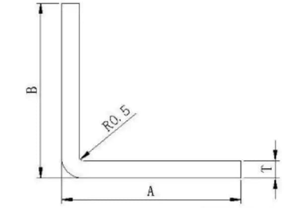
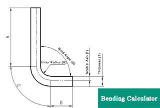
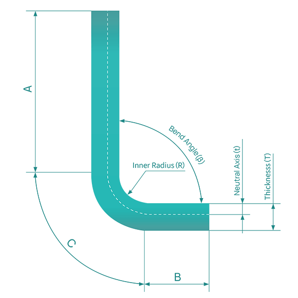
To calculate bend allowance for sheet metal, you need to consider several key parameters and use a specific formula. The parameters you need are material thickness (T), bend angle (A), inside radius (R), and K-Factor (K). The bend allowance (BA) is the arc length of the bend measured along the neutral axis of the metal plate.
The formula for calculating bend allowance is:
Where:
For example, given a bend angle (A) of 120 degrees, an inside radius (R) of 6.5 mm, material thickness (T) of 2.5 mm, and a K-factor (K) of 0.5, you can calculate the bend allowance as follows:
1. Convert the bend angle to radians if necessary:
2. Apply the values to the formula:
The calculated bend allowance (BA) is 16.23 mm. This value is then used to determine the flat length of the sheet metal required to form the desired workpiece. The flat length can be calculated by adding the lengths of the legs to the bend allowance. This ensures precise and efficient fabrication of sheet metal parts.
Bend allowance (BA) and bend deduction (BD) are two essential concepts in sheet metal bending that serve different purposes in the fabrication process. Bend allowance refers to the length of material needed to create a bend, measured along the neutral axis of the sheet metal. It accounts for the actual material used in the bend and is added to the flat length to ensure that the final dimensions of the workpiece meet design specifications.
On the other hand, bend deduction represents the amount of material that must be subtracted from the total flat length to achieve the desired bend. This deduction is necessary to compensate for the springback effect that occurs when the bending force is removed, ensuring that the final bend angle is accurate and that the dimensions of the part are maintained.
In summary, while bend allowance is added to the flat length for proper material usage during bending, bend deduction is subtracted to account for material behavior after bending, particularly the tendency to unbend slightly. Both calculations are critical for achieving precise and accurate sheet metal components.
Accurately calculating the flat length in sheet metal bending is crucial for several reasons that directly impact the quality, efficiency, and cost-effectiveness of the fabrication process.
First, precise flat length calculations ensure that the final part dimensions match the design specifications. By correctly accounting for Bend Allowance and Bend Deduction, the dimensions of the finished part will be accurate, ensuring that it fits properly within the overall assembly and meets the intended design requirements.
Second, accurate flat length calculations optimize material utilization and efficiency. By determining the exact size of the sheet metal needed before bending, fabricators can minimize waste and control costs, making the fabrication process more resource-efficient.
Third, ensuring the correct flat length is vital for the proper fit and assembly of parts. Incorrect dimensions can lead to parts that do not fit together as intended, causing assembly issues and potential rework, which can be costly and time-consuming.
Fourth, accurate calculations help maintain the stress distribution and structural integrity of the bent parts. Properly accounting for Bend Allowance and Bend Deduction ensures that the parts are bent in a way that maintains their strength and durability, which is essential for the reliability of the final product.
Fifth, consistency in fabrication is achieved through precise flat length calculations. This consistency reduces errors and rework, leading to a more efficient and reliable manufacturing process. It also ensures that each part produced meets the same high standards.
Sixth, accurate calculations compensate for the material’s springback effect, where the bent part tends to partially unbend after the bending force is removed. By incorporating the correct Bend Deduction, fabricators can achieve the desired bend angle and maintain dimensional accuracy after the bending process.
Lastly, knowing the exact dimensions required for the flat pattern simplifies the manufacturing process. It allows for streamlined operations, making it easier to produce high-quality bent components with minimal effort and error.
In summary, accurately calculating the flat length in sheet metal bending is essential for ensuring accurate dimensions, optimizing material use, achieving proper fit and assembly, maintaining structural integrity, ensuring consistency in fabrication, compensating for springback, and simplifying the manufacturing process.
In sheet metal bending calculations, the impact of different material types on the bending factor is significant and multifaceted, influencing the accuracy, quality, and efficiency of the bending process. The key areas affected include:
Material Properties:
Different materials exhibit varying mechanical properties such as yield strength, tensile strength, and elastic modulus. These properties directly influence the material’s behavior during bending, affecting the spring back phenomenon and the required bending force. For instance, high-strength steels typically require a larger bending factor compared to mild steels due to their increased resistance to plastic deformation.
Grain Structure and Anisotropy:
The crystalline structure and grain orientation of metals play a crucial role in bending behavior. Materials with a pronounced grain structure, like certain aluminum alloys, may exhibit anisotropic properties, leading to different bending factors depending on the direction of bending relative to the grain orientation. This can result in inconsistent spring back and potential defects if not properly accounted for in calculations.
Work Hardening Characteristics:
Materials with different work hardening rates, such as austenitic stainless steels versus low-carbon steels, require distinct approaches to bending factor calculations. Work hardening during the bending process can significantly alter the material’s properties, affecting the final shape and dimensional accuracy.
Thermal Expansion Coefficients:
For processes involving heat, such as hot bending or subsequent heat treatment, the material’s thermal expansion coefficient becomes a critical factor. Materials with higher coefficients may require compensation in the bending factor to account for dimensional changes during cooling.
Surface Condition and Treatments:
Surface treatments like anodizing, galvanizing, or case hardening can alter the material’s surface properties, affecting friction during bending and potentially changing the required bending factor. The presence of oxide layers or coatings must be considered in precise bending calculations.
Thickness Variations:
While material thickness itself is a key factor, the consistency of thickness across the sheet is equally important. Materials prone to thickness variations, such as certain rolled alloys, may require adaptive bending factors or more conservative calculations to ensure consistent results across the workpiece.
Strain Rate Sensitivity:
Some materials, particularly certain aluminum alloys and high-strength steels, exhibit strain rate sensitivity. This means the bending factor may need to be adjusted based on the speed of the bending operation, with faster bending potentially requiring different calculations than slower, more controlled processes.
Residual Stress State:
The presence of residual stresses in the material, which can vary based on the material type and previous processing history, can significantly impact the bending behavior. Materials with high levels of residual stress may require stress relief treatments or adjusted bending factors to achieve accurate results.
To optimize bending operations for different material types, it’s crucial to:
By carefully considering these material-specific impacts on the bending factor, manufacturers can achieve higher precision, reduce scrap rates, and optimize their sheet metal bending processes across a wide range of materials.

As the founder of MachineMFG, I have dedicated over a decade of my career to the metalworking industry. My extensive experience has allowed me to become an expert in the fields of sheet metal fabrication, machining, mechanical engineering, and machine tools for metals. I am constantly thinking, reading, and writing about these subjects, constantly striving to stay at the forefront of my field. Let my knowledge and expertise be an asset to your business.