1. Concept of Fatigue and Fracture
Fatigue: Fatigue is the progressive and localized structural damage that occurs in materials subjected to cyclic loading. It involves the initiation and propagation of microscopic cracks under stress levels significantly below the material’s yield strength.
Fatigue Fracture: Fatigue fracture is the ultimate failure of a material or component due to the cumulative effect of cyclic stresses or strains. This phenomenon occurs through three distinct stages:
- Crack Initiation: Microscopic cracks form at stress concentration points, often at surface imperfections or material discontinuities.
- Crack Propagation: Under continued cyclic loading, these cracks grow incrementally with each stress cycle.
- Sudden Fracture: When the remaining cross-section can no longer support the applied load, catastrophic failure occurs.
Key characteristics of fatigue fracture include:
- Low Stress Amplitude: Failure can occur at stress levels well below the material’s static yield strength.
- Suddenness: The final fracture often happens without warning, as the crack growth may not be visibly apparent.
- Localization: Damage is highly localized, typically originating from a single point of high stress concentration.
- Sensitivity to Defects: Material imperfections, surface roughness, and stress risers significantly influence fatigue life.
- Time-Dependent: Failure occurs after a certain number of stress cycles, which can range from thousands to millions depending on the stress amplitude and material properties.
2. Classification of fatigue fracture
- High cycle fatigue and low cycle fatigue
High Cycle Fatigue (HCF) occurs when components are subjected to relatively low stress levels, resulting in failure after more than 105 cycles. This type of fatigue is typically associated with elastic deformation and is common in components such as springs, transmission shafts, and fasteners. HCF is characterized by minimal plastic deformation and is often governed by stress-based approaches in design and analysis.
Low Cycle Fatigue (LCF), conversely, involves high stress levels leading to failure within 104 cycles or less. LCF is prevalent in components experiencing significant plastic deformation during each loading cycle, such as pressure vessels, turbine blades, and nuclear reactor components. This type of fatigue is typically analyzed using strain-based approaches due to the pronounced plastic deformation involved.
- Stress-based and strain-based fatigue analysis
Strain-based fatigue analysis is primarily associated with LCF, where plastic deformation dominates. This approach considers both elastic and plastic strain components and is crucial for materials exhibiting significant cyclic plasticity.
Stress-based fatigue analysis is generally applied to HCF scenarios, where stresses remain predominantly in the elastic range. This method is suitable for components designed to operate below the material’s yield strength.
In practice, the distinction between stress-based and strain-based fatigue can be blurred, especially in the transition region between HCF and LCF (typically 104 to 105 cycles). Many engineering components experience a combination of both regimes, leading to what is termed as composite fatigue. In such cases, advanced analytical methods incorporating both stress and strain approaches may be necessary for accurate life prediction.
- Classification according to load type
Fatigue can be further classified based on the nature of applied loads:
- Bending fatigue: Common in rotating shafts and beams subjected to cyclic bending moments.
- Torsional fatigue: Prevalent in drive shafts and other components experiencing cyclic twisting.
- Axial fatigue: Occurs in components under cyclic tension-compression loading, such as connecting rods.
- Contact fatigue: Observed in rolling element bearings and gear teeth due to repeated surface contact stresses.
- Vibration fatigue: Results from high-frequency oscillations, often seen in aerospace and automotive components.
- Fretting fatigue: Caused by a combination of cyclic loading and small-amplitude oscillatory motion between contacting surfaces, common in bolted joints and splined connections.
3. Characteristics of fatigue fracture
Macroscopically, the fatigue fracture process can be divided into three distinct stages: crack initiation, crack propagation, and final fracture.
The crack initiation stage occurs at stress concentration sites, such as surface imperfections, notches, or metallurgical discontinuities. These act as nucleation points for microcrack formation under cyclic loading conditions.
The crack propagation zone is characterized by a relatively smooth, flat surface perpendicular to the principal stress direction. This zone exhibits distinctive fatigue striations, also known as beach marks or progression marks. These concentric patterns radiate outward from the initiation site, indicating incremental crack growth with each loading cycle.
The final fracture zone represents the area where rapid, unstable crack growth occurs, leading to sudden component failure. This region typically displays a rougher texture with features such as dimples (in ductile materials) or cleavage facets (in brittle materials). Shear lips may be present at the edges, indicating localized plastic deformation.
Microscopically, the hallmark of fatigue fracture is the presence of fatigue striations, visible under high magnification. These fine, parallel lines represent the position of the crack front after each stress cycle. Additionally, depending on the material and loading conditions, other microstructural features may be observed:
- Cleavage and quasi-cleavage facets in brittle or semi-brittle materials
- Intergranular fracture along grain boundaries in materials susceptible to environmental effects or with weak grain boundaries
- Secondary cracks perpendicular to the main fracture plane
- Microvoid coalescence (dimples) in ductile materials, particularly in the final fracture zone
Understanding these macro and microscopic features is crucial for failure analysis, as they provide valuable information about the loading history, environmental conditions, and material behavior during the fatigue process.
4. Characteristics of fatigue fracture
(1) Fatigue fracture is distinguished by the absence of significant macroscopic plastic deformation during the failure process. This characteristic often results in sudden and catastrophic failure of mechanical components without prior warning signs. The lack of visible deformation makes fatigue failures particularly insidious, as they can occur without any apparent indication of impending failure, leading to unexpected and potentially hazardous breakdowns in critical machinery or structures.
(2) The cyclic stress levels causing fatigue fracture are typically well below the material’s yield strength under static loading conditions. This phenomenon is attributed to the cumulative damage mechanism of fatigue, where microscopic cracks initiate and propagate under repeated loading, even at stresses that would be considered safe in static applications. The fatigue limit or endurance limit, which represents the stress level below which fatigue failure is unlikely to occur for a given number of cycles, is often used in design to mitigate this risk.
(3) Post-failure examination of fatigue fracture surfaces reveals distinct zones that provide valuable insights into the failure process. These zones typically include:
a) Crack initiation zone: Often characterized by a smooth, semi-circular region where the fatigue crack originates, usually at a stress concentration point or material defect.
b) Crack propagation zone: Exhibits characteristic beach marks or striations, which represent the incremental growth of the crack with each loading cycle. The spacing and pattern of these markings can indicate loading history and crack growth rate.
c) Final fracture zone: Displays a rough, irregular appearance, often with evidence of ductile or brittle fracture, depending on the material properties. This zone represents the rapid failure of the remaining cross-section when it can no longer support the applied load.
5. Case analysis
A motorcycle in a factory experienced a mechanical failure after traveling 2,000 km. Upon disassembly and inspection, it was discovered that the engine crankshaft connecting rod had broken.
The connecting rod, made of 20CrMnTi, was carburized on the surface. The working principle of the connecting rod is depicted in Figure 1, where its reciprocating motion drives the rotation of two drive crankshafts.
20CrMnTi is an alloy structural steel with a carbon content of approximately 0.2%, manganese content of approximately 1%, and titanium content of approximately 1%. This material is commonly used for shaft components and requires carburizing.
Fig. 1
1. Macro inspection
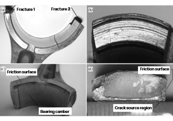
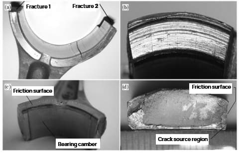
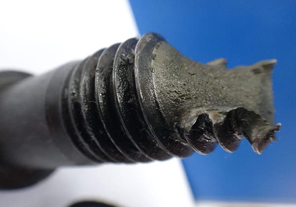
The failed connecting rod had two fractures. On the bearing camber at the fracture end of the connecting rod, many cracks parallel to the fracture are visible [Figure 3 (a)]. One side of the fracture end exhibits a strong friction trace [Figure 3 (b)], with a wear depth of 0.5mm. Additionally, a blue-gray high-temperature oxidation trace can be seen on one end of the bearing arc near the friction side [Figure 3 (c)].
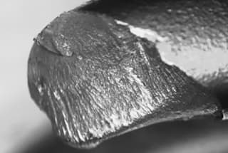
Fracture 1 is relatively smooth and flat with a worn edge, and the fatigue arc is visible in the middle [Figure 3 (d)]. However, no fatigue arc was found on fracture 2.
Fig. 2
Fig. 3
2. Scanning electron microscope analysis
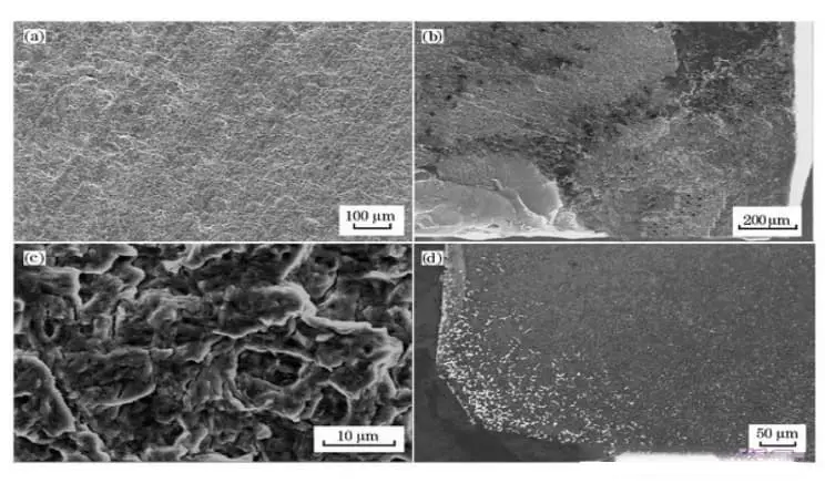
Figure 4 (a) in Fracture 1 displays a fatigue arc under a scanning electron microscope. The trend of the arc allows for the determination of the fatigue source.
The fatigue source is located in the upper right corner of Figure 4 (d). The local magnification reveals that the majority of the fine tissues in the source area have been subjected to wear, though the radial edge feature is still visible (Figure 4 (b)).
Figure 4 (c) displays fatigue stripes and secondary cracks in the fatigue growth zone.
In contrast, Fracture 2 exhibits dimples but no fatigue stripes. It can be deduced that Fracture 1 is the primary fracture and Fracture 2 is a secondary fracture.
Fig. 4
3. Chemical composition
Take samples from the connecting rod body and analyze their chemical composition, including the mass fraction (%).
The analysis results comply with the chemical composition requirements specified in GB/T3077-1999 for 20CrMnTi.
4. Result analysis
Based on the inspection results, the failed part material’s chemical composition meets the technical requirements. However, the broken end of the connecting rod shows severe friction on one side.
An analysis of the end of the bearing arc near the friction surface revealed the presence of a blue-gray oxide film, which is a mixture of black iron oxide (Fe3O4) and red iron oxide (Fe2O3) formed at temperatures above 400℃. This indicates that the friction between the connecting rod and the output shaft caused overheating in this area.
The SEM analysis of the fracture surface shows that the fatigue crack source was at the corner near the oxide film, in the high-temperature region. The combination of surface oxidation and high temperature increases the chance of crack generation and creep damage.
Additionally, friction leads to a rough metal surface, which can cause surface stress concentration and increase the possibility of fatigue. The origin of the fracture often occurs at the point of maximum tensile stress.
According to the analysis of the forces acting on the connecting rod, the largest tensile stress is present on section 1 of the fracture, making it susceptible to crack formation near the corner of the friction surface. The presence of coarse carbides in this area exacerbates the problem, as it disrupts the continuity of the matrix structure, accelerates the formation and propagation of cracks, reduces fatigue strength, and eventually leads to fatigue fracture.
The excessive carbides on the carburized surface of the connecting rod are a result of an improper carburizing process. The formation of coarse, blocky carbides is primarily due to high carbon concentration, which is most likely to occur at sharp corners of the workpiece, thereby significantly reducing its lifespan.
To prevent the formation of coarse carbides, it is crucial to strictly control the carbon potential of the carburizing atmosphere during the carburizing process. This will help avoid excessive carbon potential, which leads to the formation of coarse carbides on the workpiece surface.
5. Conclusion
The fracture of the crankshaft connecting rod is a result of fatigue fracture. The cause of the fracture is due to severe friction experienced by the connecting rod during use, which results in local stress concentration and high temperatures, reducing the fatigue strength of the material. The presence of large, blocky carbides at the corners of the connecting rod surface further accelerated the growth and spread of cracks.
6. Improvement
Reducing the roughness of the friction parts during the design stage can reduce stress concentration and improve the fatigue strength of the parts. This will also help to lower the high temperatures caused by friction and decrease the risk of creep damage.
To improve the carburizing process, it is important to address the formation of excessive carbides on the carburized surface of the connecting rod, which is caused by an improper carburizing process. Coarse, blocky carbides are primarily the result of high carbon concentration, which is most likely to form at sharp corners of the workpiece and significantly decrease its lifespan.
Therefore, strict control of the carbon potential of the carburizing atmosphere during the carburizing process is essential to prevent the formation of coarse carbides on the workpiece surface due to excessive carbon potential.
6. Methods to improve the fatigue limit or fatigue strength of materials
It is often challenging to modify the service conditions of parts, so it is essential to optimize the design of the parts to the greatest extent possible, starting with the surface effects.
By preventing surface stress concentration in structural materials and mechanical parts, the accumulation of dislocation slip is hindered and plastic deformation is restrained. This makes it more difficult for fatigue cracks to form and grow, ultimately increasing the fatigue limit or fatigue strength.
1. Measures to reduce stress concentration
In design, it is advisable to avoid square or sharp corners, holes, and grooves. In cases where the section size changes suddenly, such as on the shoulder of a stepped shaft, it is recommended to use a transition fillet with a sufficient radius to reduce stress concentration.
If increasing the radius of the transition fillet is not feasible due to structural constraints, thinner grooves or undercuts can be cut on the larger diameter shaft.
There is significant stress concentration at the edge of the tight-fitting hub and shaft fitting surface. To improve this, a load relief groove can be cut on the hub and the fitting part of the shaft can be thickened to narrow the stiffness gap between the hub and the shaft, reducing the stress concentration at the edge of the fitting surface.
At fillet welds, groove welding results in much better stress concentration compared to non-groove welding.
Related reading: Complete List of Welding Symbols
2. Enhance surface strength
To strengthen the surface layer of components, mechanical methods such as rolling and shot peening can be used. These methods form a pre-compression stress layer on the component surface, reducing surface tensile stress that is prone to crack formation and improving fatigue strength. Other methods, such as heat treatment and chemical treatment, such as high-frequency quenching, carburizing, and nitriding, can also be used.
Shot peening involves using small steel balls with a diameter of 0.1-1mm to impact the surface of the sample at a high velocity, removing sharp corners, burrs, and other stress concentrations. The surface is compressed to a depth of 1/4-1/2 of the steel ball diameter, generating residual stress on the surface of the part and restraining fatigue crack growth.
Shot peening