Imagine effortlessly slicing through metal with precision and speed. This article on fiber laser cutter operation covers essential FAQs, from safety measures to component functions, ensuring optimal performance and safety. By the end, you’ll understand how to operate and troubleshoot these high-tech machines, making your metalworking tasks efficient and effective. Ready to master the intricacies of fiber laser cutting? Let’s dive in.
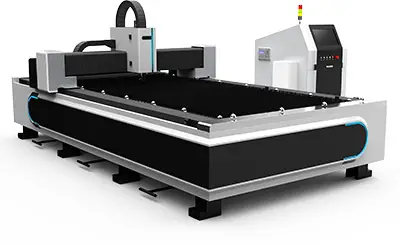
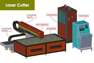
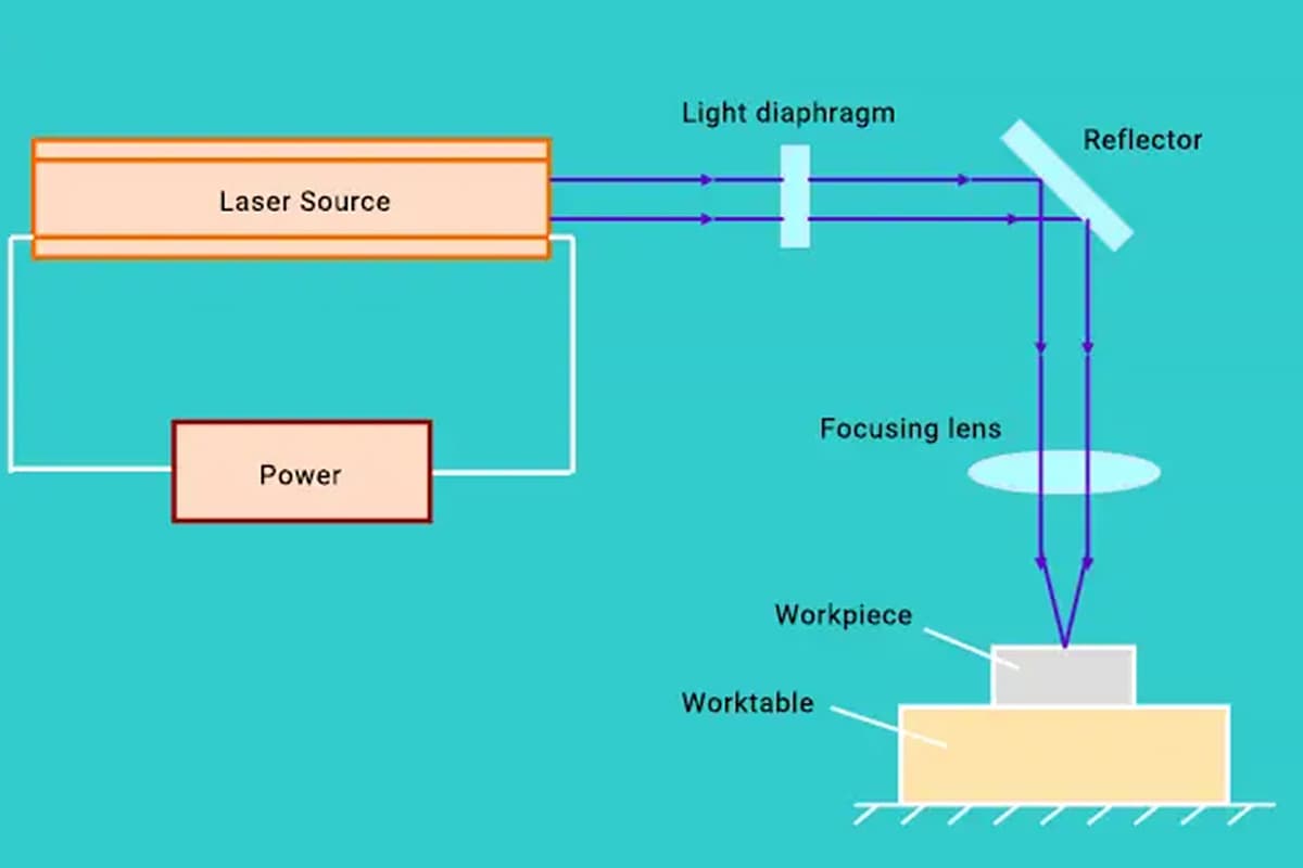
Laser Source: Generates the laser beam.
Laser Cutting Machine: Used for computer numerical control (CNC) machining.
Chiller: Cooling system for the laser beam, the reflective lens, and the cutting head.
Air Compressor: Supplies air for the laser cutting machine and auxiliary machining gases.
Dryer: Filters out water, oil, and other contaminants in the air to maintain dry air conditions.
Dust Collector: Removes dust and waste gases.
Regulator: Maintains a stable operating voltage for the device.
The meaning of the following code
| G00: | Rapid positioning | M00: | Unconditional suspension |
| G01: | Linear interpolation | M36: | Turn off followers |
| G02: | Clockwise circular interpolation | M31: | Choose air |
| G03: | Counterclockwise circular interpolation | M35: | Turn on followers |
| G04: | Pause | M10: | Open mechanical shutter |
| G10: | Empty stack | M30: | The program ends and returns to the program header |
| G50: | Scale by | M11: | Shut down mechanical shutter |
| G09: | Program read-ahead | M06: | Shut down electronic shutter |
| G51: | Workpiece rotation | M07: | Turn on electronic shutter |
| G71: | Metric programming | M14: | Turn off the auxiliary gas |
| G91: | Incremental programming | ||
| G90: | Absolute coordinates |
The height is monitored using a capacitive sensor, which is influenced by the material, the surface area in contact, and the distance between the sensor and the material.
Different nozzles have varying contact areas, so changing nozzle types requires re-calibration.
If automatic calibration fails, perform manual calibration by executing the M70 command in manual data input (MDI) mode, or switch to manual calibration.
The X-axis is adjusted by turning the upper and lower left and right adjustment screws on the laser bracket. The Y-axis and Z-axis are adjusted using three adjustment nuts on the lens holder.
Typically, rough adjustments are made using a red light, followed by fine adjustments using a cross light fork, to ensure that the front and rear spots are centered.
To prepare the flat board, place it at the end of the laser cutting machine at an angle of 30-45 degrees.
Next, remove the nozzle and adjust the scale to -5. Set the piercing delay (P199) to 0 and move the cutting head to the highest point of the board.
Bring up the program to focus the laser, manually turn on the air, and run the program. Find the spot where the burn marks on the board are the thinnest and then install the nozzle. Move the cutting head manually above this thinnest spot.
Then, unscrew the scale until the nozzle is 0.5 mm away from the surface of the plate. Record the scale value at this point, which is referred to as the “zero focus scale.”
Precautions:
Before executing the program, it’s important to verify that the direction of movement of the focus adjustment in the program matches the orientation of the board to avoid any reverse collisions.
It’s also essential to manually turn on the air before and after executing the program to prevent smoke from affecting the lens.
Once the program has finished, it’s crucial to avoid moving the Z axis until the focus has been re-established, and the board must not be bumped or jostled.
| % | Program header |
| P900002 | Program name |
| N1010 | Program annotation |
| N1020M10 | Turn on mechanical shutter |
| N1030M21 | Select laser pulse frequency |
| N1040M15 | Select continuous wave mode |
| N1040G4F30 | Pause 0.03 seconds |
| N1050G111V100 | Laser power |
| N1060U1 | Determine power |
| N1070M91 | Cancel laser open limit |
| N1080M7 | Open electronic shutter |
| N1090G4F10 | Pause 0.01 seconds |
| N1100M6 | Electronic shutter |
| N1110U0 | Cancel set power |
| N1120M11 | Turn off mechanical shutter |
| N1130M30 | The program ends and returns to the program header |
1) Beam quality:
2) Process parameters:
3) External light path:
4) External conditions:
| ROFIN: | High purity nitrogen 99.999% 5bar
Mixed gas (carbon dioxide, helium, nitrogen, carbon monoxide, oxygen, helium), designated supplier |
|---|---|
| PRC | High purity nitrogen 99.999% 5bar
High purity carbon dioxide 99.999% 5bar Pure nitrogen 99.995% 5bar |
| TK | High purity nitrogen 99.999% 5bar
High purity carbon dioxide 99.999% 5bar Note: The gas blown by the TK laser is shunted by high-purity nitrogen inside the laser. |
Before starting the machining process, it’s important to verify that the selection procedure is correct, the process parameters have been correctly named, the external auxiliary gas is available, and the position of the plate is accurate.
To prevent deformation of the sheet during machining, which could result in collisions, it’s crucial to avoid any disturbances. When the machine is in operation, the operator should remain attentive and not leave the machine, ensuring their personal safety at all times.
Focusing mirror, circular polarizer, round reflect mirror.

There are two types of slag that can appear on the lower surface of the cut material:
If the material is not cutting through, the solution is generally to slow down the speed, increase the power, and adjust the focus position.
For Carbon Steel: The hole diameter should not be less than the plate thickness if it’s below 8mm. If the hole diameter is above 10mm, it should not be less than 1.2 times the thickness of the plate.
For Stainless Steel: The hole diameter should not be less than the thickness of the plate if it’s below 4mm. If the hole diameter is above 5mm, it should not be less than 1.5 times the thickness of the plate.
If the holes exceed these requirements, they can be drilled using marking positioning or pulse slow cutting techniques.
If the machine is powered off during the machining process, the following steps should be taken after restarting the machine:
Air or auxiliary gases such as oxygen and nitrogen are not pure and contain contaminants such as moisture, particles, soot, and oil.
The exterior light path is also not clean and can become contaminated with slag during the cutting and perforation processes.
Gold, silver, copper, pure aluminum, hard alloy steel, marble, cast iron, glass, etc.
There are three methods of perforation:
Typically, conventional perforation is used on carbon steel plates that are 10mm or less in thickness, while progressive perforation is used on carbon steel plates that are 10mm or thicker. The use of burst holes is not common.
Please note that aluminum alloys should not be perforated using progressive perforation, but rather should be perforated at the focal point.
Reasons for using a burst hole include:
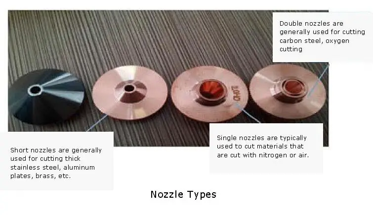
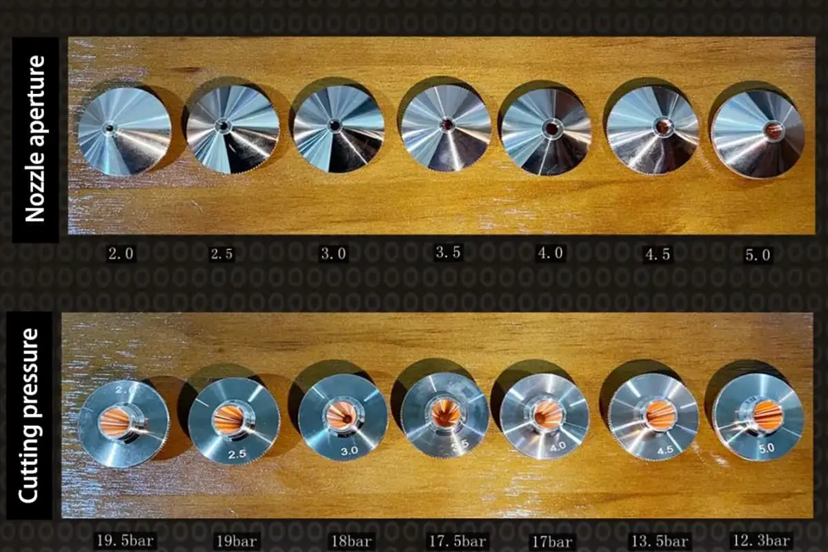
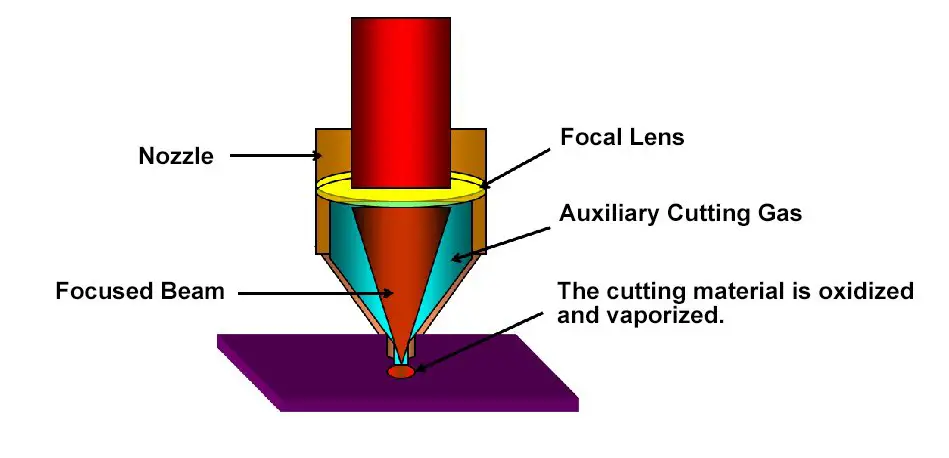
There are two types of nozzles: double-layer high nozzles and single-layer straight-bottom low nozzles. The double-layer high nozzles come in sizes 1.4, 2, 2.5, and 3.0, while the single-layer straight-bottom low nozzles come in sizes 1.5, 2.0, 2.5, and 3.0.
Typically, carbon steel uses double-layer high nozzles. For thicknesses of 8mm or less, a 1.4 nozzle is used; for thicknesses between 10-12mm, a 2.0 nozzle is used; for thicknesses between 14-18mm, a 2.5 nozzle is used; and for thicknesses between 20-25mm, a 3.0 nozzle is used.
Stainless steel and aluminum alloys, on the other hand, generally use a single-layer straight-bottom low nozzle.
| Laser Generator Type | Sheet | Power | Speed | Focus | Nozzle Dia. | Cutting Height | Cutting Gas | Air Pressure | Lens |
| mm | W | mm/min | mm | mm | mm | Bar | inch | ||
| TK2000 | MS 10 | 1800 | 1000-1200 | 1 | 2 | 1.2 | O2 | 0.8~1.0 | 7.5 |
| PRC4000 | MS 16 | 2450 | 800-1000 | 2 | 2.5 | 1.2 | O2 | 0.6~0.7 | 7.5 |
| ROFIN DC030 | SUS 8 | 2950 | 800-1100 | -8 | 2.5 | 0.65 | O2 | 20 | 7.5 |
5-inch lens:
This lens is ideal for cutting thin plates as it offers fast cutting speed and high-quality results.
7.5-inch lens:
This lens is suitable for cutting thick plates due to its small taper and high-quality cutting results. It is also effective in protecting the lens from damage.
The focus at the distal end of the optical path is lower compared to the focus at the proximal end due to the divergence angle of the laser light, which is not perfectly parallel.
To counteract the effect of different focus during the cutting process, the height of the operation panel can be adjusted by turning the adjustment knob or by adjusting the cutting speed override.
It is imperative to avoid cutting with oxygen and to instead use either nitrogen or air.
To prevent collisions and lens contamination, the distance between the nozzle and the material should be increased, and a small gap should be maintained to prevent dust buildup.
To prevent deformation and warping during cutting, techniques such as misalignment cutting, micro-connection, and shifting the cutting point can be employed.
If the size of the workpiece deviates too much due to displacement caused by deformation, it may result in a significant deviation from the desired size.
It is important to ensure that the auxiliary airflow is directed downwards at the start of the cutting process in order to effectively prevent the reversal of slag.
Oxygen is commonly used as the cutting gas and its purity is typically 99.5% or higher.
The cutting quality improves with higher oxygen purity.
Nitrogen is usually used as the cutting gas and its purity is usually 99.6% or higher. If the nitrogen purity is low, the cutting edge may appear yellow. On the other hand, if the nitrogen purity is high, the cutting edge will be brighter.
In addition, using high-purity nitrogen can also reduce the buildup of dross at the bottom edge of the cut.
When the film is facing downwards, it hinders the discharge of slag, so the film should face upwards.
When cutting with a film, it is important to be mindful of the film peeling off and potentially snagging the cutting head. A common solution is to first make a mark on the film and then proceed with the cutting process.
Once the installation is completed, replace the incorrect configuration files PA8000.com and SETUP.DAT in the FASTCAM installation directory with the correct ones.
For stainless steel that is 3mm or less in thickness, straight leads can be used. When cutting stainless steel that is 4mm or thicker, a combination of straight lines and small arcs is generally used.
For carbon steel, a circular arc is typically used.
If an undesirable phenomenon occurs, it is important to first pause and then analyze the cause before taking appropriate action to address it.
Use Bottled Gas:
While the pressure is well-guaranteed, the high cost and short usage time necessitates frequent gas changes.
Use Dewar Tank:
With easy ventilation, a long service life, and a low cost, Dewar tanks are suitable for long-term processing. (It is recommended to use high-pressure Dewar tanks, with a gasification gas volume of generally not less than 80 cubic meters.)
Use Storage Tank:
Storage tanks offer significant gas savings and a low cost, with a long-lasting usage time. Typically, liquid nitrogen is charged once every half a month, making it a one-time investment. It is recommended for use when two machines are in operation and a large amount of nitrogen is needed for auxiliary processing gas.
The programming steps for FASTCAM are as follows:
The programming steps for FASTNEST are as follows:
Check if the cutting head is raised to the highest point in case of a failure in the exchange workbench.
Z-axis negative hardware limit fault detected. To resolve this issue, press the emergency stop button, unscrew the cutting head from the hard limit switch, and then return to the zero position.
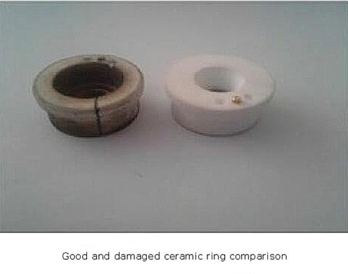
Please ensure that the cooling ceramic ring gas is functioning properly. The operator should not step away from the machine while it is in operation and should be vigilant for sudden release of plate stress and workpiece flipping. If necessary, prompt action should be taken after pausing the machine to prevent damage to the ceramic rings and cutting heads.
It is strictly prohibited to use double-layer high nozzles when cutting stainless steel or aluminum alloy with high-pressure nitrogen.

