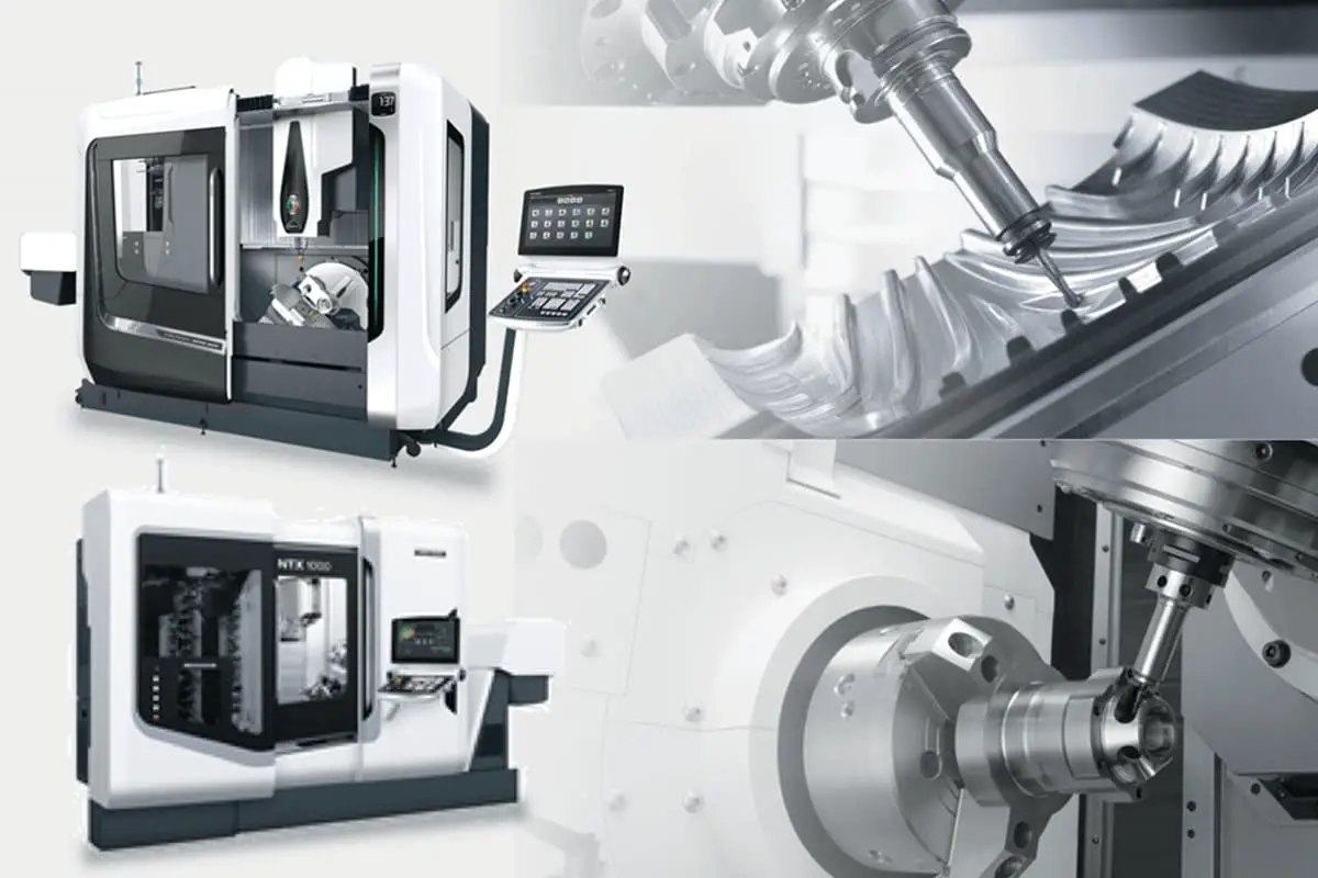
Imagine a machine so precise it can carve out the most intricate details on a jet engine part. This is the power of the five-axis CNC machine. Unlike traditional three-axis machines, it moves in five directions, allowing for unmatched precision and efficiency. In this article, you’ll discover how these machines revolutionize manufacturing, why they’re essential for complex geometries, and how they boost productivity in various industries. Prepare to see how five-axis CNC machines are reshaping the future of high-tech production.
Machine tools symbolize a nation’s level of manufacturing prowess. The pinnacle of machine tool manufacturing is represented by the five-axis linked numerical control machine tool system.
In some respects, it reflects a nation’s industrial development status. For a long time, industrialized western countries, led by the United States, have treated the five-axis linked numerical control machine tool system as a vital strategic resource, implementing an export license system.
Especially during the Cold War, they imposed blockades and embargoes on socialist bloc nations like China and the former Soviet Union. There was the “Toshiba Incident” at the end of the last century when Japan’s Toshiba Corporation sold several five-axis linked numerical control milling machines to the former Soviet Union.
The outcome was an upgrade in the manufacture of submarine propellers, making them undetectable by the sonar of American spy ships. Therefore, the United States penalized Toshiba Corporation for violating the embargo on strategic materials.
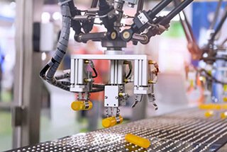
Machining centers have strong integrated processing capabilities. After a workpiece is clamped once, it can complete a significant amount of processing, with high precision.
For mid-difficulty batch parts, its efficiency is five to ten times that of regular machine tools, especially as it can accomplish many tasks that regular machine tools cannot. It is particularly suitable for the production of complex shapes and high-precision units, or small-scale, multi-variety production.
In modern manufacturing, precision machining is increasingly prevalent. High-end CNC machines and molds, which enable precision processing, sit at the forefront of the manufacturing industry chain. The quality of the mold products is largely dependent on CNC equipment.
Amid intense market competition, manufacturing requires shorter production cycles, higher processing quality, faster product retooling capabilities, and lower manufacturing technology.
To meet these conditions, more and more manufacturing companies are adopting high-end CNC machine tools—four-axis and five-axis processing machines.
We know that a three-axis machine tool only has three orthogonal movement axes (commonly defined as X, Y, and Z axes), and can only achieve three directions of linear motion freedom.
Therefore, it can process structures along the machining tool axis direction. Side structure features cannot be processed. (The three-axis machine tool has to design multiple sets of fixtures, install, locate, and clamp multiple times, decompose the overall machining, thereby lengthening the processing cycle and greatly reducing the quality.)
Unrestricted tools (or workpieces) have six degrees of freedom in space. The reality is that during metal cutting, tremendous cutting and friction forces are generated between the workpiece and the tool.
To prevent the position of the workpiece from moving, it must be clamped and fixed. Five-axis CNC machining refers to having at least five coordinate axes (three linear coordinates and two rotating coordinates) on a single machine tool, which can be coordinated and processed simultaneously under computer numerical control.
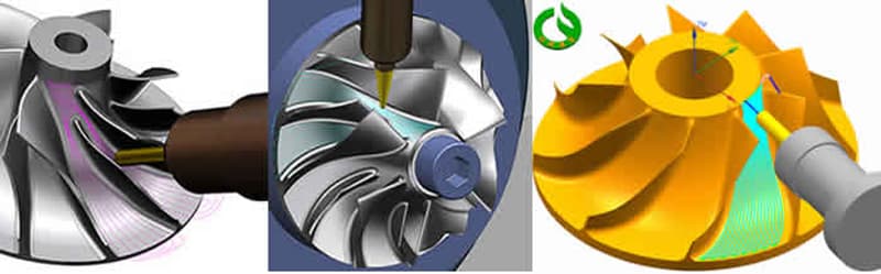
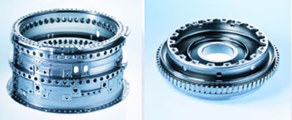
The five-axis linked CNC machine tool system is the only means for processing impellers, blades, ship propellers, heavy-duty generator rotors, turbine rotors, large diesel engine crankshafts, and more.
It’s a high-tech, high-precision machine tool specifically designed for processing complex surfaces, exerting a significant influence on a country’s aviation, aerospace, military, research, precision instruments, high-precision medical equipment industries, among others.
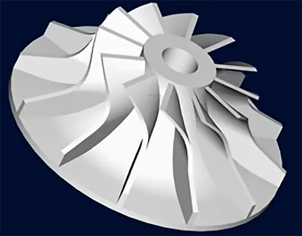
An impeller refers both to a wheel fitted with moving blades, which forms part of the rotor in impulse steam turbines, and the assembly of the wheel and the rotating blades mounted on it.
A steam turbine generator refers to a generator driven by a steam turbine. Superheated steam produced by the boiler enters the turbine, expands to do work, and turns the blades, which in turn drives the generator to produce electricity.
The spent steam after work is returned to the boiler for recycling through the condenser, circulating water pump, condensate pump, feedwater heating device, and other components.
Impeller
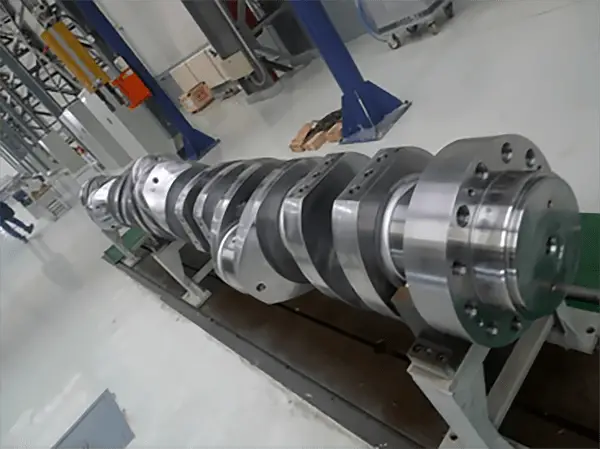
Crankshaft of a large diesel engine
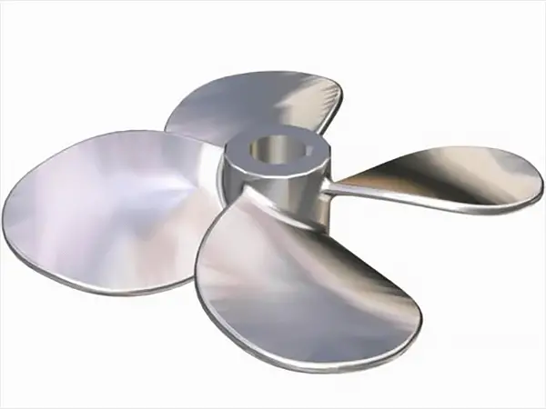
Marine Propeller
Five-Axis
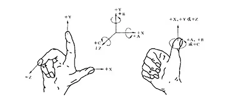
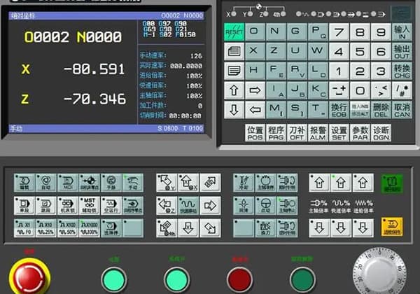
The standard coordinate system is a right-handed Cartesian system. The basic coordinate axes are three linear axes: X, Y, and Z. The rotational axes corresponding to each of these linear axes are denoted as A, B, and C respectively.
Five-axis CNC machining refers to a machine tool with at least five coordinate axes (three linear coordinates and two rotational coordinates) that can perform coordinated movements for processing under the control of a computer numerical control system.
The “axis” in a CNC machine tool denotes a motion axis, which can also be considered as a spatial coordinate axis, like the XY axis in coordinates, with each motion axis having an independent controller and motor drive system.
That is, the CNC machine tool has five servo axes (excluding the main axis) that can simultaneously interpolate (all five servo axes can move at the same time to process a single part).
Structural Varieties
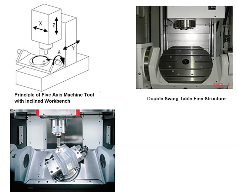
Five-axis CNC machine tools come in various structural forms, primarily divided into three main categories: worktable tilting type, spindle tilting type, and a combination of worktable/spindle tilting type five-axis machining tools.
5-axis CNC machine tool:
Tilting worktable type
Tilting spindle type
Tilting worktable/spindle type
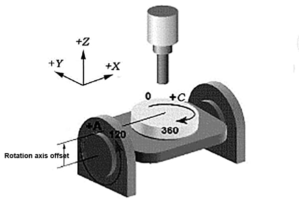
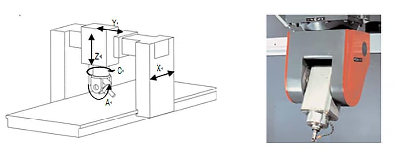
Tilted Workbench Type
This refers to the tilted workbench type. The workbench set on the machine bed can rotate around the X-axis, defined as the A-axis, typically operating within a range of +30 to -120 degrees.
A rotating table is also installed in the center of the workbench which can rotate around the Z-axis at the depicted location, defined as the C-axis, allowing for a complete 360-degree rotation.
The combination of the A-axis and C-axis enables all the five faces of the workpiece fixed on the workbench, excluding the bottom face, to be machined by the vertical spindle.
The minimum indexing values for the A-axis and C-axis are typically 0.001 degrees, which allows the workpiece to be subdivided at any angle, thereby machining inclined surfaces and holes.
When the A-axis and C-axis are coordinated with the XYZ linear axes, complex spatial surfaces can be machined, which of course requires support from high-end numerical control systems, servo systems, and software.
The advantage of this setup is that it has a relatively simple spindle structure with excellent rigidity and lower manufacturing costs.
However, the workbench generally cannot be designed too large, and its load-bearing capacity is somewhat limited, especially when the rotation of the A-axis is greater than or equal to 90 degrees, as the cutting of the workpiece will exert a significant load torque on the workbench.
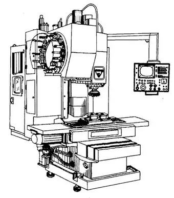
Vertical machining center
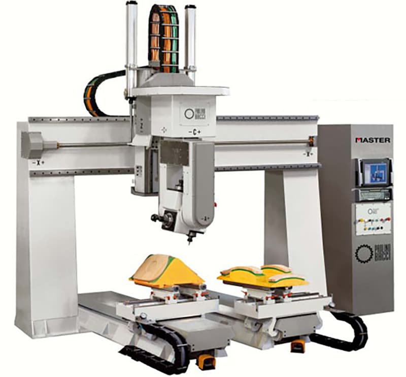
Tilted Spindle Type
The tilted spindle type features a rotating head at the front end of the main spindle, which can independently rotate around the Z-axis by 360 degrees, thus becoming the C-axis.
The rotating head also includes an A-axis that can revolve around the X-axis, typically achieving over ±90 degrees, realizing the same functionalities mentioned above.
The advantage of this setup is the flexibility it offers in spindle machining; the worktable can be designed on a substantial scale, allowing for the processing of massive aircraft bodies and engine casings on such machining centers.
Another significant advantage involves the use of a ball nose end mill for surface machining. When the tool centerline is perpendicular to the machining surface, the line speed at the tip of the ball nose end mill is zero, resulting in a poor quality surface finish due to the tip cutting.
However, by using a rotating spindle design that turns the spindle at an angle relative to the workpiece, the ball nose end mill avoids tip cutting, ensuring a certain line speed and improving the surface machining quality.
This structure is highly sought after for high-precision surface machining of molds, something difficult to attain with a rotating worktable machining center.
To achieve high rotating accuracy, high-end rotary axes are equipped with circular grating scale feedback systems, allowing for indexing accuracy within a few seconds.
Naturally, this type of spindle rotation structure is more complex and manufacturing costs are accordingly higher.
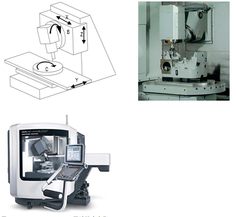
Worktable/Spindle Tilt Type
One rotational axis is on the tool side of the spindle head, and the other is on the worktable side. This type of machine tool has the most flexible arrangement of rotational axis structures, which can be any combination of A, B, and C axes.
Most of the Worktable/Spindle Tilt Type machine tools are configured with a B axis combined with a worktable rotating around the C axis. This structural arrangement is simple, flexible, and shares the advantages of both spindle tilt type and worktable tilt type machines.
The spindle of such machines can rotate to a horizontal or vertical position, and the worktable only needs to be indexed for positioning, making it easy to configure as a three-axis processing center capable of vertical and horizontal conversion.
By converting the spindle orientation and combining it with the worktable indexing, it is possible to carry out pentahedron processing on the workpiece. This results in low manufacturing costs and practical utility.
Application of Five-Axis CNC Machining
The five-axis linked machining center is ideal for processing components that are complex and require a multitude of operations.
These components demand the use of various types of conventional machine tools, numerous cutting tools and fixtures, and often require multiple setups and adjustments for successful completion.
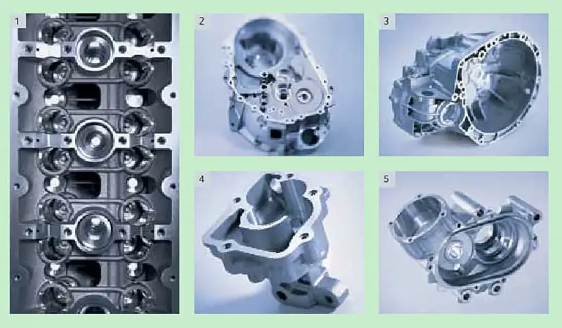
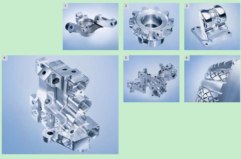
1. Enclosure-type components
Enclosure-type components generally require multi-station hole and planar machining, with high tolerance demands.
Particularly, the form and positional tolerances are rather rigorous.
These components usually undergo milling, drilling, reaming, boring, broaching, and threading operations, requiring numerous tools. The process is challenging on standard machine tools due to multiple clampings and alignments, making it hard to guarantee machining precision.
When working on enclosure-type parts, the worktable needs to rotate multiple times for machining on four horizontal faces, making the use of a horizontal machining center appropriate.
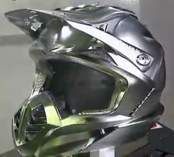
2. Complex surfaces
Complex surfaces hold a significant role in mechanical manufacturing, particularly in the aerospace industry. It is challenging, if not impossible, to fabricate complex surfaces using conventional machining methods.
Such complex surface components include a variety of impellers, spherical shapes, various curved surface forming grinders, propellers, underwater vehicle propellers, and other free-form surfaces. These components are most effectively processed on a five-axis machining center.
The milling cutter acts as an envelope surface to approximate spherical surfaces. When machining complex surfaces with a machining center, the programming workload is substantial, and most tasks require automated programming technology.
3. Irregular parts
Irregular parts, characterized by their atypical shapes, often require multi-station, mixed processing of points, lines, and surfaces. These pieces typically exhibit poor rigidity, making it challenging to control clamping deformation and to guarantee machining precision.
In fact, some parts have areas that are difficult to process using conventional machine tools. When working with machining centers, it’s prudent to adopt suitable technological measures such as single or double clamping.
Utilizing the multi-station, mixed processing capabilities of machining centers—encompassing points, lines, and surfaces—allows for the completion of multiple or all machining procedures.
4. Flanged parts
Flanged parts, components with keyways, radial holes, or end surfaces with a series of distributed holes, curved plate or shaft components, such as flanged bushings, shaft components with keyways or square ends, and plate components with an extensive array of holes, like various motor covers.
Vertical machining centers are suitable for disk parts with distributed holes on the end surface and curved surfaces, while horizontal machining centers can be chosen for those with radial holes.
5. Specialized processing
After mastering the functionality of the machining center, a combination of appropriate jigs and specialized tools enables the conduct of certain unique technical tasks.
These include engraving text, lines, and patterns on metal surfaces. By mounting a high-frequency spark power supply on the main spindle of the machining center, one can perform linear scanning surface hardening on metal surfaces.
Additionally, outfitting the machining center with a high-speed grinding head allows for the grinding of small modulus involute conical gears and various curves and surfaces.
As the founder of MachineMFG, I have dedicated over a decade of my career to the metalworking industry. My extensive experience has allowed me to become an expert in the fields of sheet metal fabrication, machining, mechanical engineering, and machine tools for metals. I am constantly thinking, reading, and writing about these subjects, constantly striving to stay at the forefront of my field. Let my knowledge and expertise be an asset to your business.
In this article, we'll explore the world of Japanese machine tool manufacturers, the unsung heroes behind many industrial innovations. Discover their cutting-edge technologies, time-tested expertise, and significant contributions to various…
Have you ever wondered about the giants of the CNC machine industry? In this fascinating blog post, we'll take a deep dive into the world of CNC manufacturing, exploring the…
In the rapidly evolving world of manufacturing, CNC machines have become indispensable. But with numerous manufacturers vying for attention, how do you choose the best? As an experienced mechanical engineer,…
In the world of precision manufacturing, German CNC machine brands stand out as titans of quality and innovation. Discover the secrets behind the success of Trumpf, DMG MORI, and Chiron,…
Ever wondered how modern factories achieve such precision and efficiency? This article explores the fascinating world of Computer Numerical Control (CNC) systems, revealing how they revolutionize manufacturing. Discover the key…
Ever wondered how the machines that shape our world are made? This article explores the top CNC lathe manufacturers, revealing the secrets behind their cutting-edge technology and global impact. Discover…
Ever wondered what powers the precision and efficiency of modern manufacturing? In this article, we explore the top CNC milling machine manufacturers, highlighting their innovations and contributions. You'll learn about…
Ever wondered how helical gears are crafted with precision using modern technology? This article delves into the intricate process of machining helical gears using a four-axis CNC machine. It covers…
In the dynamic world of manufacturing, CNC machines have transformed how we create intricate designs from raw materials. This blog delves into the fascinating realm of CNC machining, highlighting their…