Welding deformation in stainless steel can lead to significant issues in metal fabrication. The article explores various methods to control and correct these deformations, such as using copper plates, water cooling techniques, and adjusting welding parameters. By understanding these techniques, welders can enhance the quality and efficiency of their work, ensuring better performance of stainless steel components. This guide offers practical solutions and insights to help minimize deformation and improve overall welding outcomes. Read on to discover the best practices for tackling this common welding challenge.
During the fabrication of stainless steel parts, deformation of the parts is a common issue that occurs as a result of welding. This deformation is only a surface phenomenon, caused by overheating of the weld metal and the heat affected area due to the welding heat source. This overheating often results in coarse grain structures in the weld metal and the heat affected zone, which can lead to defects and negatively impact the metal’s performance.
To prevent these negative effects and control the temperature of the parts, it is important to regulate the temperature of the parts. However, waiting for the parts to cool before proceeding with the next welding process can be time-consuming and negatively impact work efficiency.
To address this issue, several solutions have been proposed. In specific welding processes, the volume of the parts is closely related to the density of the weld bead and the welding feet. For example, in the processing of stainless steel sheet parts, the heat source (arc) melts the base metal (parts) during welding, forming a molten pool. After natural cooling and crystallization, the weld seam is formed.
However, when the parts are too small, the welding heat cannot be distributed quickly, leading to distortion of the parts and affecting their appearance and shape. To solve this problem, it is necessary to address several aspects.
At present, there are two common welding methods used for stainless steel welding in most factories:
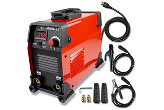
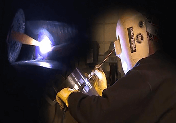
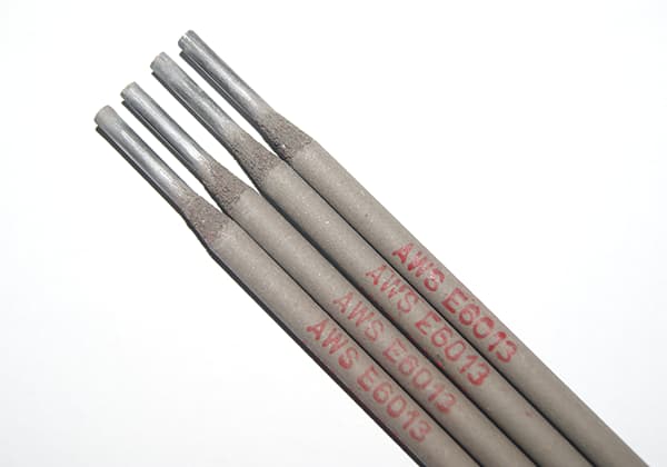
Manual Metal Arc Welding (MMAW), also known as Shielded Metal Arc Welding (SMAW) or stick welding, is a traditional welding method that demands considerable skill and expertise from the welder. This process involves creating an electric arc between a consumable electrode and the workpiece to melt and join metals.
While MMAW offers versatility in terms of material compatibility and portability, it presents several challenges:
Despite these limitations, MMAW remains relevant in various applications due to its advantages:
To optimize MMAW processes, modern developments focus on improving electrode formulations, implementing pulsed power sources, and enhancing welder training through virtual reality simulations. These advancements aim to mitigate some of the traditional limitations while preserving the method’s inherent flexibility and simplicity.
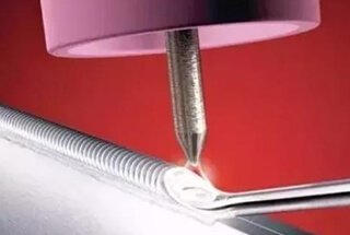
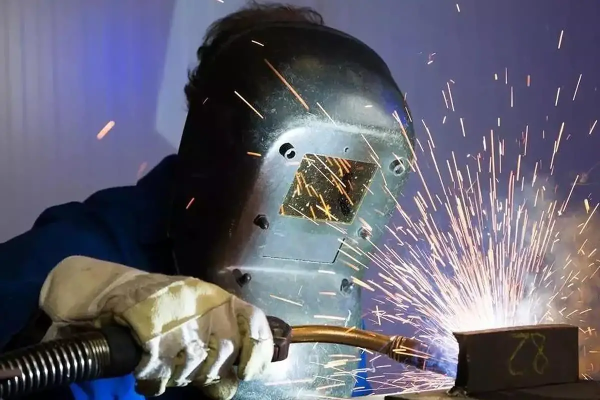
Gas shielded arc welding encompasses several techniques, including Gas Tungsten Arc Welding (GTAW) and Gas Metal Arc Welding (GMAW), which are particularly effective for stainless steel welding. These methods utilize inert gases like argon or active gas mixtures (in MAG welding) as shielding media. The advantages of gas shielded welding include rapid welding speeds, minimized heat-affected zones (HAZ), and reduced post-weld processing requirements.
For stainless steel welding, gas shielded processes are highly recommended to minimize thermal distortion and maintain material properties. When designing the welding sequence, it’s crucial to implement distortion-control techniques such as balanced welding (alternating left-right), symmetrical welding patterns, and back-step welding. These methods should follow key principles: weld from the interior to the exterior, progress from smaller to larger welds, and sequence from short to long weld runs.
Welding parameters, particularly current and voltage, significantly influence weld quality and deformation. As the thickness of stainless steel components increases, welding current should be adjusted proportionally. However, precise control of heat input is critical. Insufficient current may lead to lack of fusion or penetration defects, while excessive current can cause increased distortion, grain growth, or even burn-through in thin sections.
To optimize welding performance, parameters should be fine-tuned based on material thickness, joint design, and specific welding requirements. For instance:
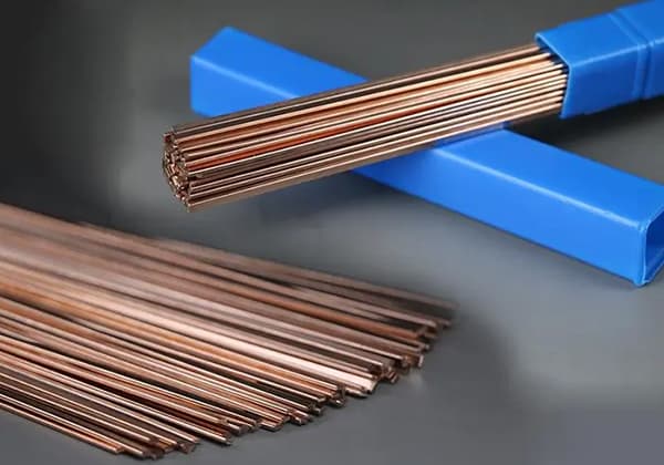
Additionally, proper selection of filler metals (e.g., ER308L for 304 stainless steel) and maintaining correct travel speeds are essential for achieving optimal weld quality and minimizing distortion in stainless steel fabrication.
For instance, in case of the welding method being L-shape, T-shape or overlapping parts in a flat plane, a copper plate (with a thickness greater than 8mm) can be added under the parts, as depicted in Figure 1.
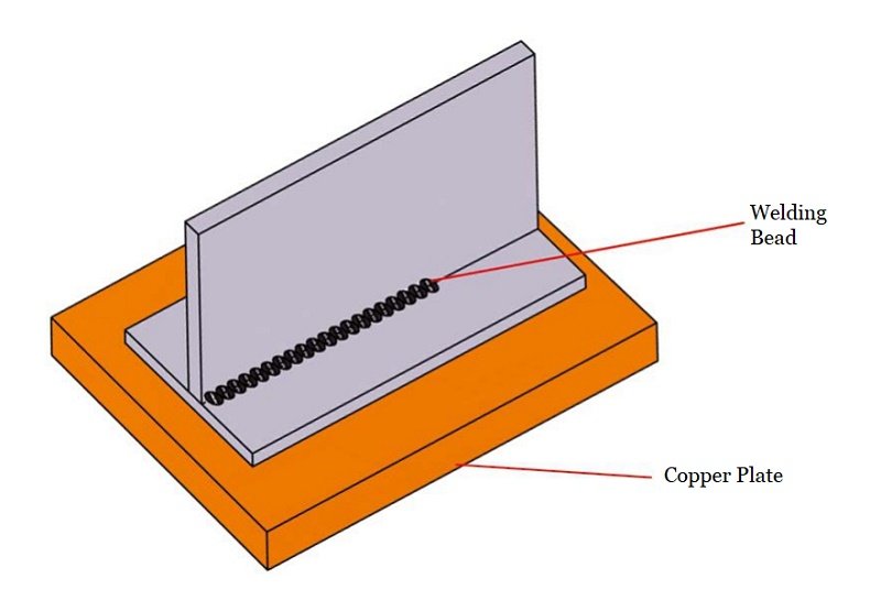
Fig.1 copper plate underparts
The heat transfer efficiency of copper is higher than that of steel, thus the use of a copper plate can facilitate the removal of welding heat and minimize thermal deformation of the parts.
If the parts are not flat or are prone to swelling, making it difficult for close contact with the copper plate, a thick cotton material with high water absorption or a soaked mat can be placed under the weld bead of the parts. This will also effectively reduce deformation.
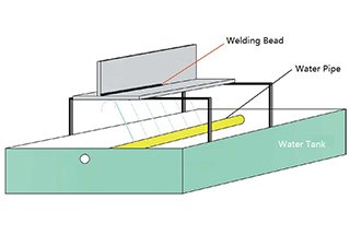
If the shape of the parts is complex or there is no space for a copper plate, the above solution may not be feasible. In such cases, the water cooling method should be employed (as shown in Figure 2).
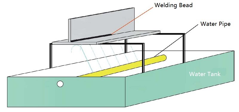
Fig.2 water cooling method
Water cooling is generally classified into two categories:
① Spray cooling:
In this method, water is sprayed on the back side of the weld bead of the parts, which is suitable for parts with larger areas. It is crucial to adjust the water current angle for T-shape or L-shape overlap to prevent water from flowing into the welding position.
The advantage of this method is that it provides efficient cooling and is convenient for mass production. However, the disadvantage is that it requires special equipment and is only suitable for single-type processed parts.
② Wet sand cooling:
The spray cooling method is not applicable for planar joint welding because it cannot ensure that water does not flow into the welding path. The wet sand cooling method can be used instead. This involves filling containers (larger than the welding parts) with sand, fully saturating the sand with water, and placing the parts flat on the wet sand before welding.
This allows the back side of the parts’ weld bead to be in full contact with the wet sand, and welding can then commence. The advantage of this method is its simple operation and suitability for all complex shapes. The disadvantage is that it is not easy to fabricate large parts.
This generally refers to welding of parts with a thickness greater than 6mm. Due to the large size of the parts, the long weld length, and high welding height (large molten pool area and extensive hot zone), bending deformation caused by thermal deformation may occur during welding. To address this issue, several measures should be taken:
① Adequate cooling measures should be prepared before welding (refer to the cooling scheme for small parts);
② Welding allowance for deformation:
Since it is difficult to achieve symmetrical welding or simultaneous welding on one side for most parts, and uneven heating will result in bending deformation during welding. To mitigate this, the deformation of the parts should be counteracted in the opposite direction of the deformation, based on the length of the parts, the thickness of the material (height of the welding bead), and the shape.
This requires experienced engineering and technical personnel and skilled workers to make judgments based on experience. Fixtures are used to fix the parts, and after fabricating the first piece, fine adjustments are made based on the actual effect.
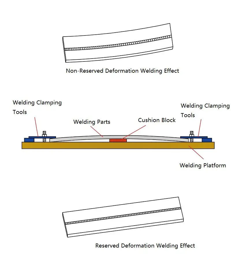
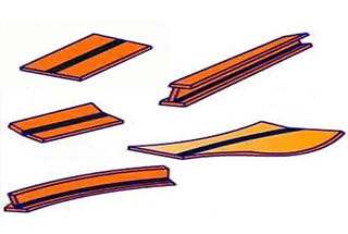
Fig.3 weld allowance for deformation
Stainless steel welding presents unique challenges compared to ordinary carbon steel due to its lower thermal conductivity and higher electrical resistance and thermal expansion coefficient. These properties result in slower heat dissipation and greater thermal deformation during the welding process.
Post-fabrication, even if surface deformation is not immediately apparent, stainless steel parts may experience dimensional changes during transportation, vibration, movement, or temperature fluctuations. These changes can significantly impact the appearance, dimensional accuracy, and performance of the welded components.
Consequently, stress relief is crucial for large stainless steel parts after fabrication, particularly for thick sections (characterized by high weld penetration and large molten pools) and components with multiple weld beads. Stress relief can be achieved through two primary methods: natural aging or artificial aging.
Natural aging, while commonly used for large castings, is generally unsuitable for welded stainless steel parts due to its lengthy and unpredictable process, making it difficult to control and integrate into modern manufacturing timelines.
Artificial aging, a more controlled approach, can be further categorized into heat treatment aging and vibration aging:
Due to these benefits, vibration aging has become the preferred stress relief method for many stainless steel fabrication facilities. It offers an efficient, economical, and non-invasive solution to enhance the long-term stability and performance of welded stainless steel components without compromising their structural integrity or surface finish.
Welding deformation remains an inherent challenge in stainless steel fabrication, significantly impacting the precision and functionality of welded components. Mitigating these effects demands a comprehensive approach that integrates advanced welding technologies, optimized process parameters, and strategic planning. Key focus areas include:
Effective control of welding deformation necessitates a synergistic collaboration between engineering teams and welding operators. This partnership should leverage theoretical principles, empirical data, and real-time process feedback to develop adaptive fabrication strategies. By integrating cutting-edge simulation tools with shop floor expertise, manufacturers can iteratively refine their approach to minimize distortion.
Furthermore, embracing Industry 4.0 technologies such as in-situ monitoring systems and machine learning algorithms can provide real-time insights into the welding process, enabling dynamic adjustments to maintain optimal conditions. This data-driven approach not only enhances product quality but also contributes to continuous process improvement and knowledge accumulation.
By rigorously addressing welding deformation through this multifaceted approach, manufacturers can consistently produce high-precision stainless steel components that meet increasingly stringent tolerances and performance criteria across various industrial applications.

