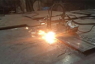
Ever wondered how to achieve perfect flame cuts in metalwork? This guide sets the standard for manual, semi-automatic, and automatic flame cutting operations. You’ll learn essential procedures, quality requirements, and safety measures to ensure precision and safety in your cutting tasks. Discover how to prepare, execute, and troubleshoot your flame cutting processes for optimal results.

To further standardize the workshop’s flame cutting work and regulate the management of flame cutting operations, this set of rules is established.
These rules apply to our company’s control over standardized flame cutting operating procedures, (including the cutting methods of manual torches, semi-automatic cutting machines, and CNC flame cutting machines).

JB/T5000.2-2007 “General Technical Conditions for Heavy Machinery, Part 2: Flame Cut Parts”,
JB3092-82 “Technical Requirements for Flame Cutting Surface Quality.
4.1.1 Inspect the workspace and clean up any obstructions to cutting. Flammable or explosive items should not be near the workspace.
4.1.2 Inspection of flame cutting equipment:
a) Check for any leaks in the hose connecting the gas source and the cutting equipment, and whether the gas source is functioning correctly.
b) Check if the torch is working properly. The cutting wind lines for all torches should be straight, clear cylinders, otherwise, a pass needle should be used to clean the torch’s inner hole.
c) Check if the longitudinal travel mechanism, horizontal adjustment mechanism, and up-and-down adjustment mechanism of the torch are in normal condition.
4.1.3 According to the workshop’s layout for cutting, carefully check the width, length, and thickness of the steel plate to be cut, and whether the material meets requirements.
4.1.4 Lift the steel plate to the appropriate cutting position.
4.1.5 Adjust the position of the steel plate, ensuring that the two sides of the plate are parallel to the cutting direction. Make sure the entire steel plate is in a horizontal uniform state, and clean the surface of the steel plate.
4.1.6 When manually cutting or semi-automatically cutting, draw lines at the end of the steel plate according to the width of the material to be cut from the layout.
a) Consider the width of the cutting seam when drawing lines.
b) The permitted tolerance of cutting strip width: for H-beams, the tolerance range for the wings and web is 0~-2mm; for box column wings and webs, the tolerance range should be 0~+2mm.
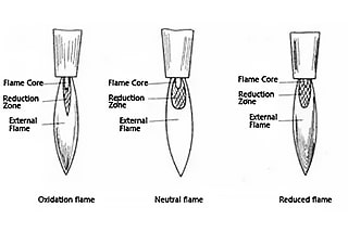
4.2.1 A neutral flame should be used for preheating and cutting.
4.2.2 Choose an appropriate nozzle size and cutting process parameters according to the thickness of the steel plate being cut.
Follow the parameters specified in Table 1.
Table 1: Selection Table for Flame Cutting Machine (Oxygen-Propane) Cutting Process Parameters
| Cutting Nozzle Spec. & Model | Cutting Oxygen Aperture Dia. (mm) | Cutting Thickness (mm) | Cutting Speed (mm/min) | Oxygen Pressure (MPa) | Propane Pressure (MPa) | Kerf Width (mm) | Oxygen Consumption (m³/h) | Preheating Time (s) |
| GKJ3-1 | 0.6mm | 5-10 | 750-600 | 0.7 | 0.04 | ≤1mm | ||
| GKJ3-2 | 0.8mm | 10-20 | 600-450 | 0.7 | 0.04 | ≤1.5mm | ||
| GKJ3-3 | 1mm | 20-40 | 450-380 | 0.7 | 0.04 | ≤2mm | 10-13 | |
| GKJ3-4 | 1.25mm | 40-60 | 380-320 | 0.7 | 0.04 | ≤2.3mm | 12-15 | |
| GKJ3-5 | 1.5mm | 60-100 | 320-250 | 0.7 | 0.04 | ≤3.4mm | 16-17 | |
| GKJ3-6 | 1.75mm | 100-150 | 250-160 | 0.7 | 0.04 | ≤4mm | 18-22 | |
| GKJ3-7 | 2mm | 150-180 | 160-130 | 0.7 | 0.04 | ≤4.5mm | 24-32 | |
| GKJ3-8 | 2.3mm | 180-210 | 130-110 | 0.7 | 0.04 | ≤5mm | 31-40 | |
| GKJ3-9 | 2.6mm | 210-250 | 110-90 | 0.7 | 0.04 | ≤5.5mm | ||
| GKJ3-10 | 3.2mm | 250-300 | 90-60 | 0.7 | 0.04 | ≤7mm | ||
| GKJ3-1A | 0.6mm | 5-10 | 560-450 | 0.5 | 0.04 | ≤1mm | ||
| GKJ3-2A | 0.8mm | 10-20 | 450-340 | 0.5 | 0.04 | ≤1.5mm | ||
| GKJ3-3A | 1mm | 20-40 | 340-250 | 0.5 | 0.04 | ≤2mm | 10-13 | |
| GKJ3-4A | 1.25mm | 40-60 | 250-210 | 0.5 | 0.04 | ≤2.3mm | 12-15 | |
| GKJ3-5A | 1.5mm | 60-100 | 210-180 | 0.5 | 0.04 | ≤3.4mm | 16-17 | |
| GKJ3-6A | 1.75mm | 100-150 | 180-150 | 0.5 | 0.04 | ≤4mm | 18-22 | |
| GKJ3-7A | 2mm | 150-180 | 150-120 | 0.5 | 0.04 | ≤4.5mm | 24-32 | |
| GKJ3-8A | 2.3mm | 180-210 | 120-110 | 0.5 | 0.04 | ≤5mm | 31-40 | |
| GKJ3-9A | 2.6mm | 210-250 | 110-80 | 0.5 | 0.04 | ≤5.5mm | ||
| GKJ3-10A | 3.2mm | 250-300 | 80-45 | 0.5 | 0.04 | ≤7mm | ||
| G03-00# | Φ0.8 | 5–20 | 690 | 0.3 | 0.02 | 1.97 | ||
| G03-0# | Φ1.0 | 20-35 | 690-630 | 0.3 | 0.02 | 1.2 | 2.84 | 10-13 |
| G03-1# | Φ1.2 | 35-45 | 630-530 | 0.4- | 0.02 | 1.4 | 4.38 | 12-15 |
| G03-2# | Φ1.4 | 45-60 | 530-450 | 0.4- | 0.02 | 1.6 | 6.2 | 14-17 |
| G03-3# | Φ1.6 | 60-100 | 450-300 | 0.5 | 0.03 | 1.9 | 8.1 | 16-19 |
| G03-4# | Φ1.8 | 100-130 | 300-240 | 0.5 | 0.03 | 2.2 | 9.25 | 18-25 |
| G03-5# | Φ2.0 | 130-160 | 240-200 | 0.6 | 0.03 | 2.4 | 12.38 | 24-32 |
| G03-6# | Φ2.4 | 160-220 | 200-170 | 0.6 | 0.04 | 2.9 | 15.36 | 31-42 |
| G03-7# | Φ3.0 | 220-260 | 170-130 | 0.7 | 0.04 | 22.26 | ||
| G03-8# | Φ3.2 | 260-320 | 130-90 | 0.7 | 0.04 | 24.4 | ||
| G03-9# | Φ3.6 | 320-380 | 90-60 | 0.8 | 0.06 | 42.42 | ||
| G03-10# | Φ4.0 | 380-450 | 60-40 | 0.8 | 0.07 | 55.16 | ||
| Suitable for cutting carbon steel plates with a carbon content of ≤0.45%. | ||||||||
4.2.3 Cutting Operation Procedure
a) Adjust the positions of each cutting torch to ensure they are directly above the cutting seams. The distance of the cutting torch from the surface of the steel plate should ideally be between 10 and 15mm.
b) Adjust the cutting speed as per the requirements of Table 1.
c) Ignite the cutting torch: First, open the combustible gas valve and light the cutting torch using an igniter. Next, open the preheating oxygen valve, then adjust the flame to neutral. The flame temperature should be adjusted according to the thickness of the steel plate being cut.
d) Prior to starting the cut, preheat the edges of the steel plate. When the preheating area of the steel plate turns red, open the cutting oxygen valve. When the iron oxide slag flies out with the flow of oxygen, it indicates that the cut-through has been achieved. Press the travel button to start the test cut.
e) After the test cut has proceeded for 10 to 20mm, promptly close the cutting oxygen and move the cutting torch back beyond the end of the steel plate. Check whether the width of the steel plate meets the requirements. If not, adjust the position of the cutting torch accordingly.
f) After preheating again, reopen the cutting oxygen. Press the travel button of the cutting torch to officially start cutting.
g) During the cutting process, continually observe if the flame from each cutting torch is normal and whether the cutting speed is appropriate. Adjust as necessary.
h) During the cutting process, sometimes the cutting nozzle may become blocked due to overheating, causing the cutting torch to backfire. In this case, quickly close the preheating oxygen valve to extinguish the backfire. If the backfire still exists at this point, quickly close the combustible gas valve or pull out the combustible gas hose on the cutting torch to discharge the backfired flame gas.
i) Upon reaching the end point of the cut, promptly close the cutting oxygen valve, then close the combustible gas valve, and finally, close the preheating oxygen valve.
j) Remove all slag from the cut surface of the completed steel plate.
k) After all cutting work is complete, promptly close the valves for the combustible gas supply and oxygen pipeline.
4.3.1 Quality requirements for cut surface:
a) The cut surface should be smooth and clean.
b) Iron oxide slag should be easy to remove.
c) The gaps in the cut should be narrow and consistent in width.
d) The edges of the cut steel plate should not be melted.
4.3.2 Process parameters greatly affect the quality of gas cutting.
The relationship between common gas cutting section defects and process parameters is shown in Table 2.
Table 2 Analysis of Gas Cutting Surface Defects and Causes
| Types of Defects | Cause of occurrence | Illustrated explanation | |
| Rough Cutting Surface | a. The cutting oxygen pressure is too high. b. The choice of cutting nozzle is inappropriate. c. The cutting speed is too fast. d. The preheating flame’s energy is excessive. |  | |
| Notches on the Cutting Surface | a. The cutting process was interrupted, resulting in a poor restart seam. b. The surface of the steel plate has thick scale and rust. c. The cutting machine’s movement is unsteady. |  | |
| Inward Dents on the Cutting Surface | a. The cutting oxygen pressure is too high. b. The cutting speed is too fast. |  | |
| Slanted Cutting Surface | a. The cutting torch is not perpendicular to the plate surface. b. The air line is skewed. c. The cutting oxygen pressure is low or the nozzle size is too small. |  | |
| Beaded Edge on the Cutting Surface | a. The steel plate surface has oxidation scale and rust. b. The cutting nozzle is too close to the steel plate, with the flame being too intense. |  | |
| Melted Edge on the Cutting Surface | a. The preheating flame is too strong. b. The cutting speed is too slow. c. The cutting nozzle is too close to the plate. |  | |
| Residue Adhesion on the Lower Cutting Edge | The cutting speed is either too fast or too slow.The nozzle’s size is too small.The cutting oxygen pressure is too low. |  |
4.3.3 Measures to Ensure Cut Quality
4.3.3.1 The pressure of the cutting gas should be appropriate: if too high, the cut will be too wide; if too low, the oxidized slag will not be blown away, and the material may not be completely cut through. Melted slag in the cut tends to stick together and is hard to remove.
4.3.3.2 The heat power of the preheating flame should be moderate: if too high, the edges of the steel plate cut will melt; if too low, the cutting process could be interrupted, resulting in an uneven cut surface.
4.3.3.3 The cutting speed should be appropriate to ensure that the melted slag and flame move vertically downwards. If the cutting speed is too high, it may not cut through and could even cause oxidized slag to float upwards, leading to a backfire. If the cutting speed is too slow, the cut widens and efficiency declines.
4.3.3.4 The distance between the cutting torch and the steel plate being cut should be appropriate. If too low, the cutting nozzle is prone to blockage and backfire. If too high, the kerf widens, and it becomes difficult to ensure the dimensions of the cut material.
4.3.3.5 The cutting torch should be kept clean, and the nozzle should be kept clean and smooth at all times.
4.4.1 In the cutting area, the storage of flammable and explosive materials is strictly prohibited.
4.4.2 The combustible gas cylinders used for cutting should be kept as far away from the oxygen interface as possible, more than 5 meters away from open flames and sparks, and should be placed upright and securely.
4.4.3 The use of pressure reducers should follow these rules:
a) Pressure gauges and pressure reducers must undergo regular inspection as required. All pressure gauges and pressure reducers in use must be within their inspection cycle and bear a valid inspection mark.
b) Pressure reducers should be dedicated; those for different gases should not be interchanged.
c) When installing a pressure reducer, it’s crucial not to tighten it by hammering the nut.
d) Before installing a pressure reducer, check whether the bottle mouth and threads on the reducer are intact, and clean off dirt and grease.
e) When opening the gas cylinder valve, operators should avoid the outlet of the bottle valve and check for any leaks and whether the pressure gauge pointer is responsive.
f) If the pressure gauge of the pressure reducer malfunctions, its use should be immediately stopped and a request made to the department to replace it with a qualified pressure gauge.
4.4.4 Oxygen and propane hoses must not be interchanged, and hoses should be kept away from red-hot metals to prevent them from burning and causing a fire; aging or cracked hoses should be replaced promptly.
4.4.5 In the event of a hose rupture or fire during the use of combustible gas hoses, the flame of the cutting torch should be extinguished first, and gas supply should be stopped; when an oxygen hose catches fire, the valve on the oxygen pipeline should be closed quickly, and it is strictly prohibited to extinguish the fire by bending the oxygen hose.
4.4.6 The rail should be kept clean, wiped at least once a week, then lubricated with machine oil. Before starting the machine each day, the rail and both sides should be inspected; nothing should obstruct the movement of the cutting torch holder.
4.4.7 The gas passage of the cutting torch must not be contaminated with grease. Operators are not allowed to handle oxygen cylinders and pressure reducing valves with greasy gloves to prevent explosions when oxygen comes into contact with grease.

