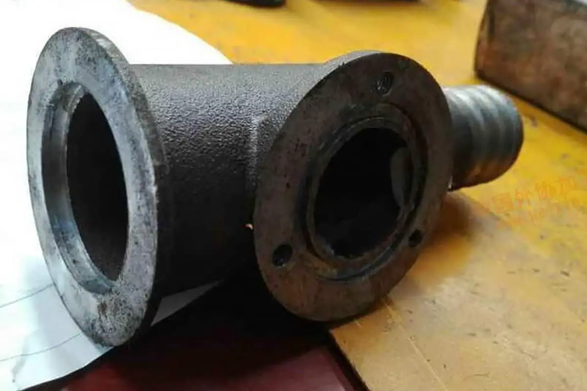
Imagine welding without flames, sparks, or even melting metal. Friction welding offers just that, using the heat generated by friction to seamlessly bond materials. This method, known for its efficiency and strength, is revolutionizing the way industries approach joining metals. In this article, discover how friction welding works, its various types, and the factors influencing its success. Get ready to explore a process that could change the future of manufacturing.
(1) The Principle of Friction Welding
Friction Welding: It is a pressure welding method that uses the heat generated by the mutual friction in the relative motion of the welding parts’ contact surfaces to achieve reliable material connection.
The welding process occurs under pressure, where the materials to be welded generate friction due to relative motion, causing the interface and nearby temperatures to rise and reach a thermoplastic state.

As the upset force comes into play, the interface oxide film is shattered, the material undergoes plastic deformation and flow, and a joint is formed through interface element diffusion and recrystallization metallurgical reactions.
The welding process does not add filler metal, does not require flux, and does not use protective gas. The entire welding process only takes a few seconds.
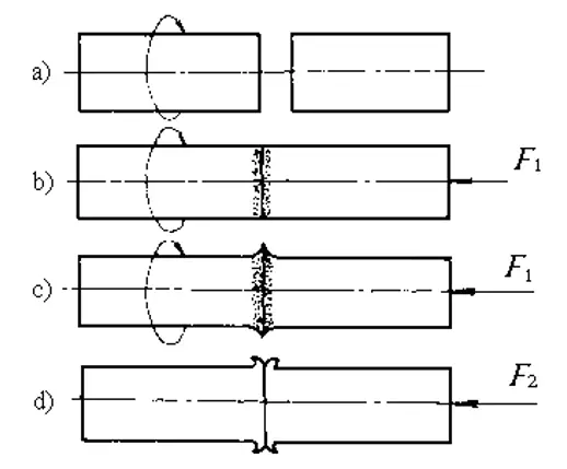
High-speed relative friction under pressure between the joint surfaces of the two weldments produces two effects:
1) It destroys the oxide film or other contamination layer on the joint surface, exposing clean metal;
2) It generates heat, quickly forming a thermoplastic layer on the joint surface. Under the subsequent friction torque and axial pressure, these shattered oxides and part of the plastic layer are extruded out of the joint surface to form flash, and the remaining plastic-deformed metal constitutes the weld metal. The final upsetting makes the weld metal undergo further forging, forming a good-quality welding joint.
From the welding process, it can be seen that the friction welding joint is formed below the melting point of the welded metal, so friction welding belongs to the solid-state welding method.
(2) Classification of Friction Welding:
Friction welding can be classified into three types: workpiece rotation, stationary workpiece, and other movements. These three can be further divided as follows:
1. Workpiece rotation:
2. Stationary workpiece:
3. Other movements:
This is a common type of friction welding. During the welding process, the workpiece is continuously driven by the spindle motor to rotate at a constant speed until it reaches the specified friction time or friction deformation amount. The workpiece then immediately stops rotating and begins the forge welding.

The rotating end of the workpiece is clamped in the flywheel. At the start of the welding process, the flywheel and the rotating end of the workpiece are accelerated to a certain speed, then the flywheel is disengaged from the main motor.
At the same time, the movable end of the workpiece moves forward. After the workpiece contacts, it starts to friction heat. During the friction welding heating process, the flywheel is braked by the friction torque, and the speed gradually decreases. When the speed reaches zero, the welding process ends.

An annular ring with a beveled surface is mounted on the end surface of a pipe with a split opening. During friction welding, the ring is rotated and radial frictional forces are applied to the two pipe ends. When the friction is finished, the rotation of the ring stops, and upset pressure is applied.

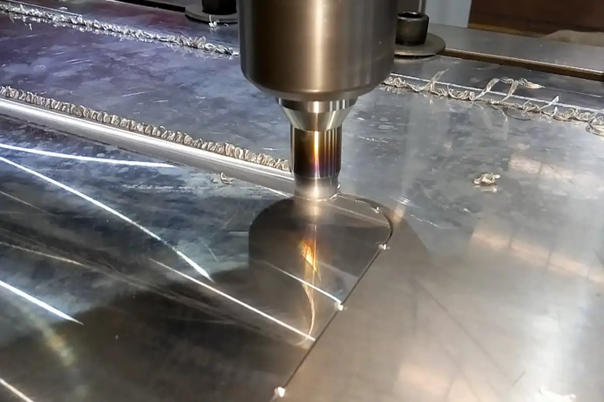
The working principle of friction stir welding is as follows: A stir needle of a certain shape made of high-temperature resistant hard material is rotated and inserted deeply into the edge of two materials to be welded.
The stirring head adjusts rotation, generating a large amount of friction heat at the edges of the two weldments, thus forming a metal plastic softening zone at the connection.
This plastic softening zone is stirred and squeezed under the action of the stirring head, and flows backward along the weld seam with the rotation of the stirring head, forming a plastic metal flow. In the cooling process after the stirring head leaves, it is squeezed to form a solid phase welding joint.

The surfacing metal rod rotates at high speed and applies frictional pressure to the parent metal. Due to the large volume of the parent material, good heat conduction, and fast cooling speed, the friction surface moves from the interface between the surfacing metal and the parent material to the surfacing metal side.
At the same time, the surfacing metal solidifies and transitions onto the parent metal to form a surfacing weld. When the parent material rotates or moves relative to the surfacing metal rod, a surfacing weld seam is formed on the parent material.

One of the two workpieces to be welded is fixed, and the other moves back and forth at a certain speed, or the two workpieces move relative to each other. Under the action of pressure, the interface of the two workpieces generates heat due to friction, thus achieving welding.

Orbital friction welding is a newly developed welding method, mainly used for welding non-circular cross-section workpieces.
For straight-line orbital friction welding, the workpiece travels along a straight-line track, with a certain amplitude and frequency ensuring that the vibration speed reaches the required value, making the welding surface do relative repetitive vibrational friction.
For circular orbital friction welding, each mass point of the workpiece moves with the same radius and speed, moving along the circular orbit to make the welding surface do relative movement friction. After the joint is heated to the welding temperature, the frictional movement of the workpiece is stopped, and upsetting is carried out.


