Have you ever wondered how massive steel structures are cut with such precision? Gas cutting, a remarkable yet often unsung process, has revolutionized the metal fabrication industry. In this article, we’ll delve into the science behind gas cutting, explore its applications, and discover how it has transformed the way we shape and create with metal. Get ready to be amazed by the power and versatility of this cutting-edge technology!
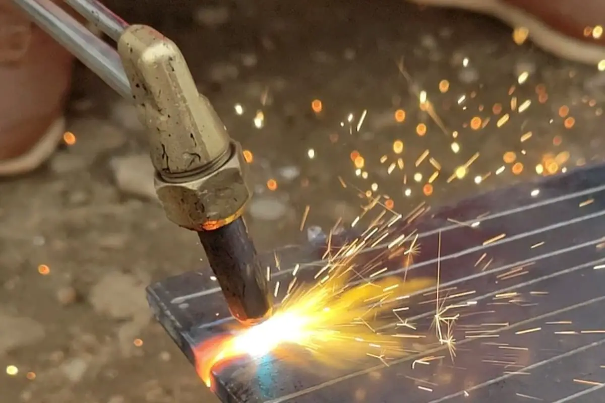

Oxy-fuel cutting, also known as flame cutting or oxyacetylene cutting, is a highly efficient thermal cutting process widely used in equipment manufacturing. This method leverages the exothermic reaction between pure oxygen and heated metal to create precise cuts in ferrous materials.
The simplicity and ease of operation of oxy-fuel cutting equipment make it particularly suitable for processing carbon steel and low alloy steel. It excels in producing accurate cuts in straight lines, circles, and complex shapes, with the capability to handle a wide range of material thicknesses, typically from 5 mm to 300 mm.
Recent advancements in CNC technology, photoelectric tracking systems, and high-performance cutting nozzles have significantly enhanced the automation potential of oxy-fuel cutting. These innovations have led to improved cutting precision, increased productivity, and reduced operator dependency.
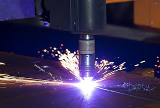
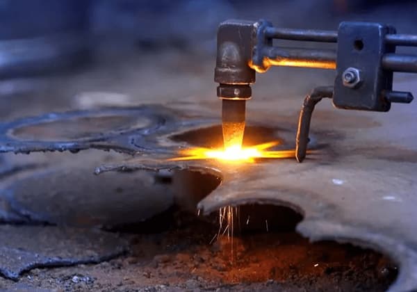
The oxy-fuel cutting process utilizes a torch that mixes a fuel gas (typically acetylene) with oxygen to generate a high-temperature flame. This flame preheats the metal at the cutting point to its ignition temperature (approximately 870°C for mild steel). Subsequently, a jet of pure oxygen is directed at the preheated area, initiating a rapid oxidation reaction. The resulting molten oxide is expelled from the kerf by the force of the oxygen jet, creating a clean cut.
For optimal cutting performance, the oxygen purity should exceed 99.5%. While acetylene is the preferred fuel gas due to its high flame temperature (3160°C) and cutting efficiency, alternative fuel gases such as propane, natural gas, or MAPP gas can be used in specific applications or when acetylene is not available.
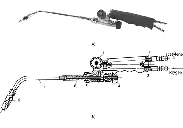
The cutting torch is the critical component in oxy-fuel cutting equipment. Its design influences cutting speed, quality, and overall efficiency. Modern torches often incorporate features like multi-flame preheating, high-speed nozzles, and ergonomic designs to enhance performance and operator comfort.
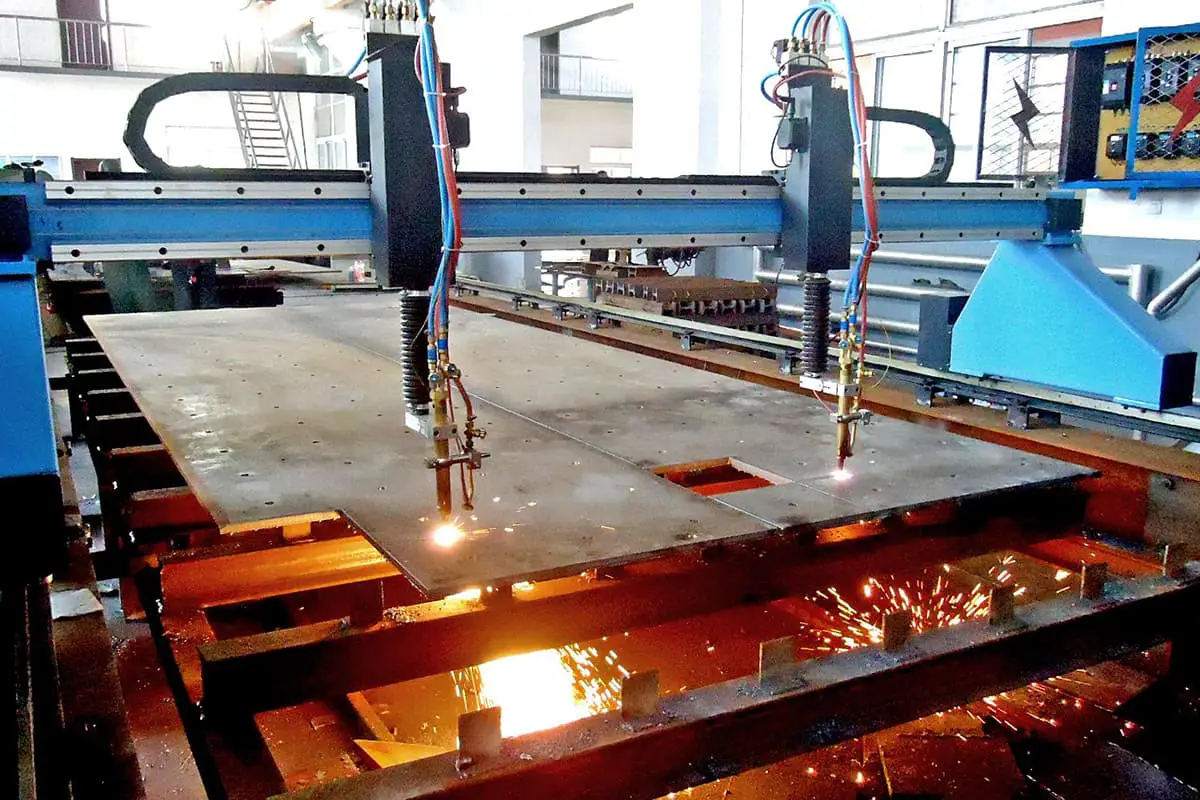
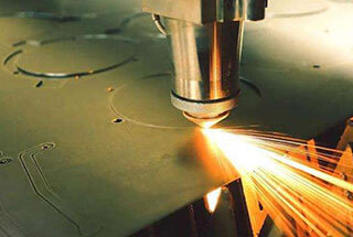
Oxy-fuel cutting systems range from portable manual setups using gas cylinders to sophisticated automated machines. Advanced systems may include multiple cutting heads, computer numerical control (CNC), and integrated CAD/CAM software for complex cutting operations. These automated systems are particularly beneficial in mass production scenarios, offering increased throughput and consistency.
Key advantages of oxy-fuel cutting include:
However, it’s important to note that oxy-fuel cutting is limited to ferrous materials and may not be suitable for high-precision applications or cutting thin materials (below 5 mm) where plasma or laser cutting might be more appropriate.
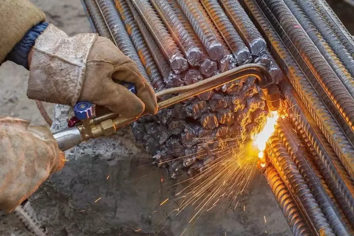
Gas cutting, also known as oxy-fuel cutting, is a thermal cutting process that uses a combination of fuel gas and oxygen to cut through metals. The mechanism involves preheating the metal to its ignition temperature and then rapidly oxidizing it with a high-purity oxygen stream. This process creates a continuous, precise cut through the workpiece.
The cutting mechanism occurs in the following stages:
For successful gas cutting, the following conditions must be satisfied:
Gas cutting machines are automated systems that supersede manual cutting torches, offering enhanced productivity, superior cut quality, reduced operator fatigue, and improved cost-effectiveness in metal fabrication processes.
1) Semi-automatic gas cutting machine:
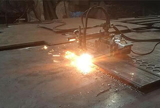
This system comprises a compact, self-propelled carriage that guides the cutting nozzle along a predetermined track. While the carriage movement is automated, the trajectory requires manual adjustment, allowing for a balance between automation and operator control.
2) Profile gas cutting machine:
a) Gantry type: Utilizes a robust gantry structure where the cutting nozzle traverses along the workpiece profile via precision-engineered wheel mechanisms, ensuring stability and accuracy in complex cutting operations.
b) Swing arm type: Employs an articulated arm system that pivots to guide the cutting nozzle, offering enhanced flexibility for intricate profile cutting, particularly suited for curved or irregular shapes.
3) Photoelectric tracking gas cutting machine:
This advanced system incorporates photoelectric sensors to detect and follow pre-drawn patterns or templates. The cutting torch is automatically guided along the profile, enabling high-precision automated cutting of complex shapes with minimal operator intervention.
4) CNC gas cutting machine:
Computer Numerical Control (CNC) represents a sophisticated control methodology where digital instructions govern machine operations. In CNC gas cutting systems, a computer interprets and executes programmed cutting paths, controlling parameters such as torch movement, cutting speed, and gas flow. This technology enables:
Modern CNC gas cutting machines often incorporate multi-axis control, allowing for bevel cuts and 3D profiling, further expanding their capabilities in advanced metal fabrication processes.
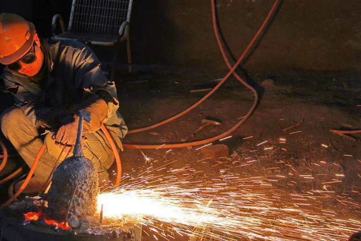
The gas cutting process mainly includes the pressure of the cutting oxygen, cutting speed, efficiency of the preheating flame, the tilt angle of the cutting nozzle and workpiece, and the distance between the cutting nozzle and the workpiece.
1) Pressure of the cutting oxygen:
It is influenced by the thickness of the workpiece, the type of cutting nozzle, and the purity of the oxygen.
When cutting thin materials, a smaller cutting nozzle size and lower oxygen pressure should be selected.
The purity of the oxygen has a significant impact on cutting speed, gas consumption, and cut quality.
2) Cutting speed:
It depends on the thickness of the workpiece and the shape of the cutting nozzle. As the thickness increases, the cutting speed decreases.
The cutting speed should not be too fast or too slow, as it can result in excessive drag and incomplete cuts.
The correctness of the cutting speed is mainly judged based on the amount of drag in the cut.
3) Efficiency of the preheating flame:
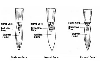
A neutral flame or a slightly oxidizing flame is used for preheating in gas cutting, and a carburizing flame should not be used.
The efficiency of the preheating flame is expressed in terms of the consumption rate of the combustible gas per hour.
The efficiency of the preheating flame is related to the thickness of the workpiece.
4) Tilt angle of the cutting nozzle and workpiece:
The tilt angle of the cutting nozzle and workpiece is determined primarily by the thickness of the workpiece.
The tilt angle of the cutting nozzle and workpiece directly affects the cutting speed and drag.
A backward tilt can reduce drag and increase cutting speed.
5) Distance between the cutting nozzle and the workpiece surface:
The distance between the cutting nozzle and the workpiece surface should be determined based on the length of the preheating flame and the thickness of the workpiece, generally around 3 to 5mm.
When δ<20mm, the flame can be longer, and the distance can be increased accordingly.
When δ>=20mm, the flame should be shorter, and the distance can be reduced.
6) Quality requirements of gas cutting cuts:
The surface of the gas cutting cut should be smooth and clean, with consistent coarse and fine lines. The iron oxide slag produced during gas cutting is easy to detach. The gap of the gas cutting cut should be narrow and consistent, and there should be no melting of the steel plate edges.
Evaluation criteria and grading of cut quality:
a) Surface roughness: Surface roughness refers to the distance between the peaks and valleys on the cutting surface (average of five arbitrary points), indicated by G.
b) Flatness: Flatness refers to the level of unevenness along the cutting direction perpendicular to the cutting surface. It is calculated as a percentage of the thickness δ of the cut steel plate, indicated by B.
c) Degree of upper edge melting: This refers to the extent of melting or collapse during the gas cutting process, manifested by the presence of collapsed corners and the formation of intermittent or continuous droplets or melted strips, indicated by S.
d) Slag hanging: Slag hanging refers to the iron oxide adhering to the lower edge of the cut surface. It is classified into different grades based on the amount of adhesion and the difficulty of removal, indicated by Z.
e) Maximum defect spacing: Maximum defect spacing refers to the appearance of grooves on the cut surface along the cutting line direction due to vibrations or interruptions, causing a sudden decrease in surface roughness. The depth of the groove is between 0.32mm to 1.2mm, and the width of the groove does not exceed 5mm. Such grooves are considered defects. The maximum defect spacing is indicated by Q.
f) Straightness: Straightness refers to the gap between the straight line connecting the starting and ending points along the cutting direction and the crown-like cloud cutting surface. It is indicated by P.
g) Perpendicularity: Perpendicularity refers to the maximum deviation between the actual cut surface and the perpendicular line to the surface of the metal being cut.
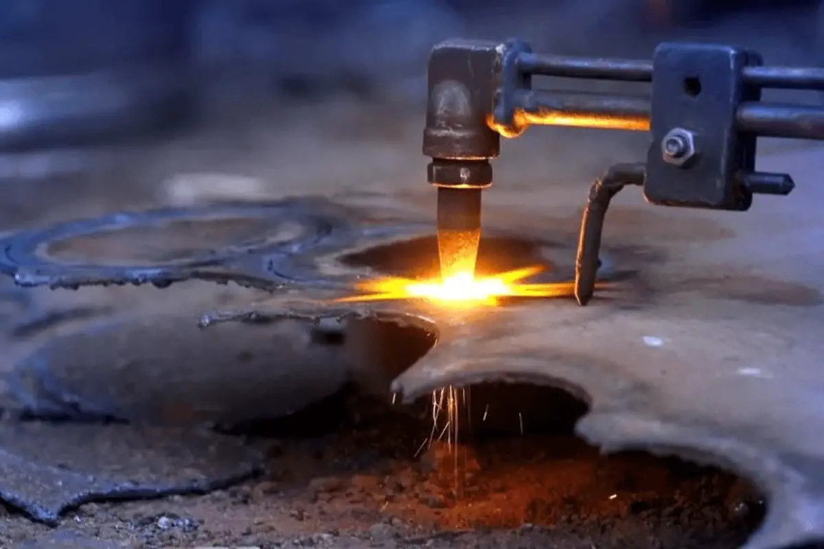
7) Causes and prevention methods of common defects:
(1) Excessive width and rough surface of the cut:
This is caused by excessive cutting oxygen pressure. When the cutting oxygen pressure is too low, the slag cannot be blown away, causing the slag to stick together and difficult to remove.
Prevention: Adjust the cutting oxygen pressure to an appropriate level for the desired cut width and surface roughness.
(2) Uneven surface or melting of edges:
This is caused by excessive preheating flame intensity or slow cutting speed. Insufficient preheating flame intensity can lead to interruptions in the cutting process and an uneven surface.
Prevention: Ensure an appropriate preheating flame intensity to achieve a regular and even cut.
(3) Excessive drag after cutting:
This occurs when the cutting speed is too fast, resulting in excessive drag and incomplete cuts. In severe cases, the slag may fly upwards and cause reheat.
Prevention: Adjust the cutting speed to an appropriate level to achieve proper cutting without excessive drag.
8) Ways to improve the surface quality of the cut:
(1) Proper cutting oxygen pressure:
Excessive cutting oxygen pressure can result in a wider cut and a rough surface, while wasting oxygen. Insufficient cutting oxygen pressure can cause the slag to stick together and be difficult to remove.
Solution: Adjust the cutting oxygen pressure to an appropriate level for the desired cut quality.
(2) Proper preheating flame intensity:
Excessive preheating flame intensity can lead to melting of the edges on the cut surface, while insufficient intensity can cause interruptions in the cutting process and an uneven surface.
Solution: Ensure an appropriate preheating flame intensity for a smooth and even cut.
(3) Proper cutting speed:
When the cutting speed is too fast, it can result in excessive drag, incomplete cuts, and the slag flying upwards, leading to reheat. When the cutting speed is too slow, the edges of the steel plate may melt, waste gas, and thinner plates may experience excessive deformation and adhesion, making post-cut cleaning difficult.
Solution: Adjust the cutting speed to an appropriate level for the desired cut quality.
Advantages of Gas Cutting
Disadvantages of Gas Cutting
Extensively utilized in steel fabrication for precision plate cutting and weld bevel preparation, enabling efficient joining processes in structural steel work and heavy equipment manufacturing.
Highly effective for removing gating systems in large-scale castings, capable of handling substantial thicknesses exceeding 300mm. This makes it invaluable in foundry operations and the production of heavy industrial components.
Primarily employed for cutting various grades of carbon steel and low-alloy steel, offering a cost-effective solution for thick-section materials where other cutting methods may be less efficient or economical.
When processing high-carbon steel or low-alloy steel grades prone to quenching, special precautions are necessary to prevent edge hardening or cracking:
Gas cutting finds extensive use in shipbuilding, construction, and demolition industries, where its ability to cut thick plates and irregular shapes is advantageous.
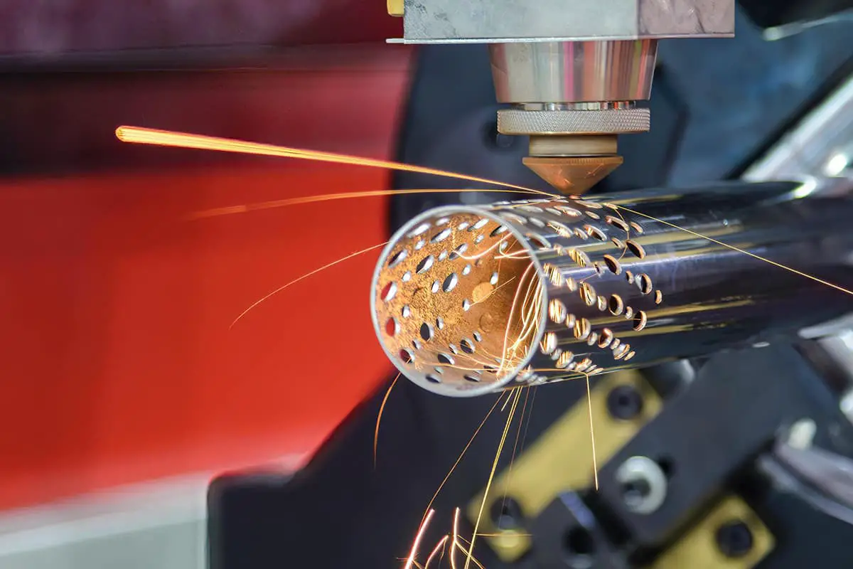
In pipe fabrication, gas cutting is employed for creating precise bevels and saddle cuts, facilitating proper fit-up in pipeline construction and pressure vessel manufacturing.

