Have you ever wondered about the hidden complexities behind the seemingly simple steel beams that support our buildings and bridges? In this fascinating blog post, we delve into the intricacies of calculating the weight of H-beams and I-beams, as explained by a seasoned mechanical engineer. Discover the common pitfalls, industry standards, and the science behind these essential components of modern construction.
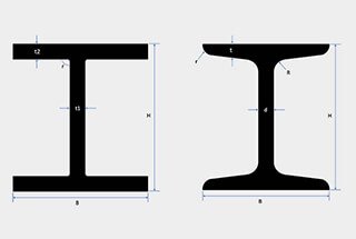
H-beams are structural elements widely used in construction due to their high load-bearing capacity and structural stability. They are characterized by their H-shaped cross-section, which consists of two parallel flanges connected by a vertical web. This design allows H-beams to effectively resist bending and twisting forces, making them suitable for various structural applications.
H-beams are specified by several key dimensions:
For example, an H-beam designated as “H-beam 200x200x8x12” indicates a height and flange width of 200 mm, a web thickness of 8 mm, and a flange thickness of 12 mm.
Calculating the weight of an H-beam is a critical task in construction and engineering. Accurate weight calculations ensure structural stability and material efficiency, which are essential for safe and cost-effective designs.
Online H beam weight calculator is invaluable tools for engineers, architects, and construction professionals, enabling them to quickly and accurately determine the weight of H beams. The calculator streamline the process, ensuring precise weight calculations crucial for structural design and load analysis.
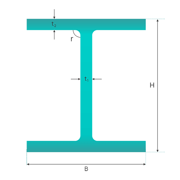
Note:
To convert h-beam sizes from millimeters to inches, use our millimeters to inches calculator.
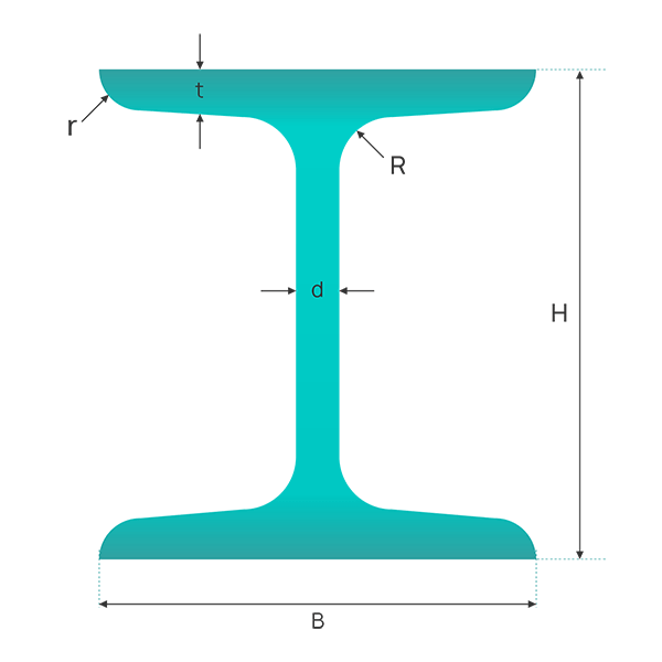
Note:
If you need to find I-beam sizes in inches, you can use our millimeters to inches calculator for accurate conversion results.
If you’re looking for a quicker and more convenient solution to determining the weight of H-beams and I-beams, you can use the H-beam weight chart and I-beam weight chart provided.
These charts allow you to easily check the weight of various-sized H-beams and I-beams, eliminating the need for repetitive calculations using a calculator.
Please refer to the following article for additional calculations on various metal weights.
Common sources of error when calculating the weight of H-beams and I-beams include the following:
Discrepancies between theoretical and actual weight: When using calculators or theoretical weight charts, there can be a certain degree of error between the derived result and the actual weight. For example, the theoretical weight displayed by the H-beam calculator may differ from the actual weight by 0.2% to 0.7%. This error may be due to the simplification of actual conditions in the calculation method, neglecting the real state of the material and minor changes during the manufacturing process.
Errors in the manufacturing and processing stages: Weight discrepancies in H-beams are unavoidable issues during manufacturing and processing. This includes precision losses during heat treatment, cutting, welding, and other processes, as well as unevenness within the material itself.
Error range stipulated by national standards: For welded H-beams, the discrepancy between the theoretical weight and the actual weigh-in should comply with national standards, such as the error range specified by GB/T 33814-2017, which is +/-6% or +/-4%. This means that this error range needs to be considered during design and calculation.
Negative tolerance phenomenon in materials: Some materials on the market may exhibit a negative tolerance phenomenon, where the theoretical weight calculation data is greater than the actual weigh-in. This requires adjusting the calculation by multiplying it by a coefficient to align the theoretical weight with the actual weigh-in.
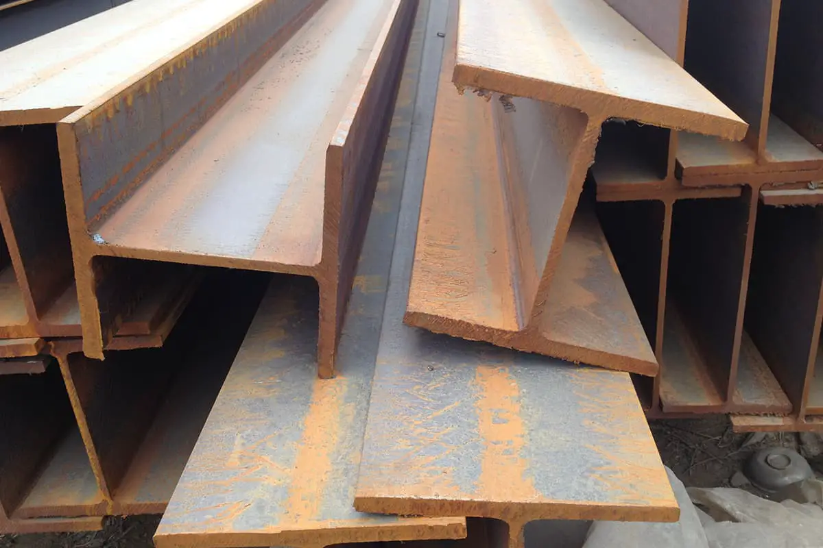
H-beams, characterized by their “H” shape, are vital components in numerous construction and industrial projects due to their robust bending resistance, straightforward assembly, and efficient strength-to-weight ratio. Accurate weight calculations of H-beams are crucial for ensuring structural integrity, safety, and efficiency.
H-beams are designed to handle significant loads and provide structural support in various projects. Their design allows them to bear bending forces effectively, making them ideal for use in large structures. The weight of an H-beam is a critical factor that influences its load-bearing capacity and the overall stability of the structure.
In residential and commercial buildings, H-beams are used as columns, beams, and supports. Accurate weight calculations help determine the overall structure weight, affecting foundation requirements and material costs. For example, the weight of an H-beam can be calculated using the formula:
Where ( h ) is the height, ( b1 ) and ( b2 ) are the widths of the upper and lower flanges, ( t1 ) is the thickness of the flanges, and ( b3 ) and ( t2 ) are the width and thickness of the web plate, respectively. These calculations ensure the structure can support the intended loads without compromising safety or efficiency.
H-beams are extensively used in bridge construction due to their strength and stability. Accurate weight calculations ensure the structural integrity and load-bearing capacity of the bridge. For instance, in a case study of a bridge project, engineers calculated the weight of H-beams to ensure they could support dynamic loads and environmental stresses. The size and material properties of the H-beam, such as its cross-sectional area and steel density, were critical factors in these calculations.
In industrial settings like warehouses and factories, H-beams support heavy machinery and storage systems. The weight calculation helps in planning logistics and installation, ensuring the structure can support the intended loads. For example, in a factory setup, accurate weight calculations of H-beams allowed for the design of a framework that could handle heavy equipment without compromising safety.
H-beams are used in power plants to support heavy equipment and infrastructure. Accurate weight calculations ensure that the beams can handle significant loads and stresses, contributing to the overall stability and safety of the plant. Engineers use these calculations to design frameworks that can withstand the operational demands of power plants.
The load-bearing capacity of an H-beam is a crucial aspect of its application. This capacity depends on the size of the H-beam, its material properties, and the configuration of the load. Larger H-beams with greater depth and flange width generally have higher load-bearing capacities. The material composition, typically structural steel, also plays a significant role in its strength and ductility.
Engineers employ structural engineering principles and mathematical formulas to determine the load-bearing capacity and weight of H-beams. For example, the weight per meter can be calculated using the aforementioned formula and then multiplied by the beam length to get the total weight. Tools like finite element analysis (FEA) and computer-aided design (CAD) software are used to predict structural behavior under various load scenarios. FEA helps in analyzing complex structures by breaking them down into smaller elements, while CAD allows for precise design and modifications.
The simplicity of H-beam construction and on-site assembly contributes to cost savings and increased efficiency in construction projects. Knowing the exact weight of the H-beams helps in planning transportation and installation processes, significantly reducing costs and improving project timelines. Accurate weight calculations enable project managers to allocate resources effectively, minimize waste, and enhance overall project efficiency.
By understanding the practical applications and importance of accurate H-beam weight calculations, engineers and construction professionals can ensure the success and safety of various construction and industrial projects.
Interpreting H beam specifications accurately is essential for ensuring the correct application and performance of these structural elements in construction and engineering projects. Understanding the dimensions, designations, and properties of H beams helps professionals select the right beam for their specific needs.
H beams are designated based on their key dimensions and weight per unit length. This designation provides critical information about the beam’s size and load-bearing capacity.
The depth, also known as the height, is the vertical distance from the top to the bottom of the beam’s cross-section. A greater depth increases the beam’s ability to resist bending forces, enhancing its load-bearing capacity. For example, an H beam with a depth of 300 mm can support larger loads and longer spans compared to a beam with a depth of 200 mm.
The flange width is the horizontal distance across the flanges. Wider flanges improve the beam’s stability and resistance to lateral bending. For instance, a beam with a flange width of 200 mm provides better lateral support than one with a flange width of 150 mm, making it suitable for applications where lateral stability is crucial.
The flange thickness impacts the beam’s ability to withstand shear forces and bending moments. Thicker flanges increase the beam’s overall strength. For example, an H beam with a flange thickness of 20 mm can handle higher shear forces compared to one with a flange thickness of 12 mm.
The web thickness is the measure of the vertical section connecting the two flanges. A thicker web enhances the beam’s load-bearing capacity and resistance to shear forces. For example, an H beam with a web thickness of 10 mm is stronger and more suitable for heavy loads than one with a web thickness of 6 mm.
The cross-section of an H beam is characterized by its H shape, where two parallel flanges are connected by a central web. This design provides a balanced structure with a high strength-to-weight ratio, making H beams suitable for various load-bearing applications.
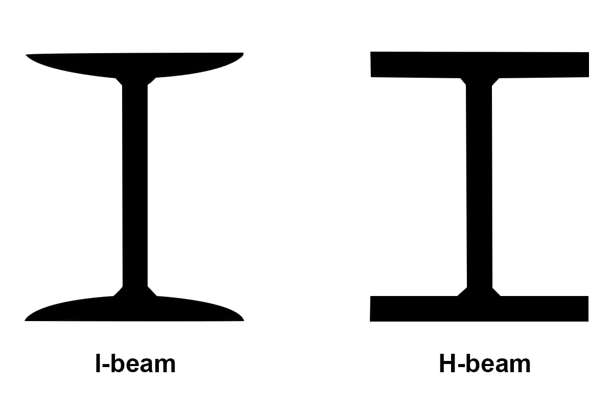
Unlike I beams, H beams feature flanges that are parallel and of equal thickness. This design extends the flanges further from the web, enhancing the beam’s bending resistance and stability.
H beams are generally heavier than I beams due to their larger size and thicker web and flanges. This increased weight allows them to support heavier loads and cover longer spans, making them ideal for large-scale construction projects such as commercial buildings, bridges, and high-rise structures.
The weight per unit length is a critical specification, indicating how much the beam weighs for each meter or foot of its length. For example, an H beam designated as “H10x30” weighs 30 pounds per foot. This information helps engineers calculate the total weight of the beam for given lengths and assess its suitability for specific applications.
H beams are typically manufactured through a hot rolling process, where steel billets are heated and passed through a series of rollers to achieve the H shape. This process ensures uniformity and strength. Alternatively, H beams can be fabricated as built-up units, with the flanges welded to the web. Built-up units offer greater flexibility in design but may incur higher costs and potential variations in structural integrity due to welding.
The mechanical properties of H beams, such as the moment of inertia and section modulus, are critical for determining their performance under load.
The moment of inertia measures the beam’s resistance to bending and is influenced by the beam’s cross-sectional dimensions. A higher moment of inertia indicates greater resistance to bending. For example, an H beam with a larger depth and flange width will have a higher moment of inertia compared to a smaller beam.
The section modulus is a measure of the beam’s ability to withstand bending stresses. It is calculated based on the cross-sectional area and shape of the beam. A higher section modulus indicates a greater ability to resist bending. For example, a beam with a section modulus of 500 cm³ can handle more bending stress than one with a section modulus of 300 cm³.
H beams are commonly used as load-bearing columns in commercial buildings, platforms, and bridges. They are also utilized in heavy-duty construction projects such as skyscrapers and foundation support due to their high strength and stability.
In commercial buildings, H beams serve as load-bearing columns, supporting floors and roofs and transferring loads to the foundation. For example, H beams used in the construction of a high-rise building provide the necessary support to handle vertical loads and resist lateral forces from wind and seismic activity.
H beams are used in platforms and bridges, where they provide the necessary support to handle dynamic loads from vehicles and pedestrians. For instance, in bridge construction, H beams can span long distances without intermediate supports, ensuring the stability and durability of the structure.
By understanding the specifications and characteristics of H beams, engineers and construction professionals can accurately select and use these beams in various applications, ensuring the structural integrity and safety of their projects.
Related reading:

