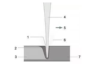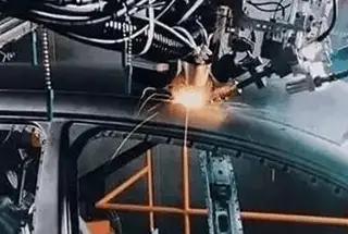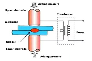
Ever wondered how laser welding transforms metalwork? This article unveils the secrets of laser welding, focusing on the crucial parameters that ensure precision and strength. From adjusting laser power to mastering swing width, you’ll uncover the essential techniques that make laser welding a game-changer in the industry. Get ready to enhance your understanding and skills!
Laser welding thickness is a crucial aspect of the welding process that determines the quality and strength of the weld. Understanding the factors that influence the thickness achievable in laser welding helps in optimizing the process for different materials and applications.
Laser welding is a high-precision process widely used in various industries due to its ability to create strong, clean welds with minimal distortion. It is particularly valuable in applications where precision and control over the welding parameters are essential. The thickness of the weld is a key parameter that influences the mechanical properties and overall integrity of the welded joint.
The power of the laser directly affects the depth of penetration into the material. Higher laser power can weld thicker materials by providing the necessary energy to melt and fuse deeper layers. For example, welding stainless steel with a thickness of 10 mm may require a laser power of around 5 kW, while thinner materials like 2 mm stainless steel might only need 1 kW. Conversely, lower laser power is suitable for thinner materials to avoid burn-through and excessive melting.
Different materials have varying properties such as thermal conductivity, absorption coefficient, and melting point, which influence how they respond to laser welding. For instance, aluminum, with its high thermal conductivity, requires higher laser power and slower welding speeds compared to stainless steel to achieve the same thickness. Copper, with its high reflectivity, demands specialized laser sources or surface treatments to ensure efficient energy absorption.
The speed at which the laser moves across the material impacts the heat input and, consequently, the weld thickness. Slower welding speeds allow more energy to penetrate the material, resulting in deeper welds. For example, reducing the welding speed from 3 m/min to 1 m/min can significantly increase the penetration depth in materials like aluminum and stainless steel. Faster speeds are used for thinner materials to prevent overheating and distortion.
The position of the laser focus relative to the material surface is critical. For thicker materials, the focus is typically set above the weldment to achieve better penetration. For thinner materials, the focus is set below the weldment to minimize the heat-affected zone and prevent warping. Adjusting the focus position by just a few millimeters can markedly affect the quality and depth of the weld.
The diameter of the laser beam affects the energy density. A smaller beam diameter provides a higher energy density, suitable for welding thinner materials. For example, a beam diameter of 0.2 mm might be used for thin-sheet metal applications, while a larger beam diameter of 0.6 mm is beneficial for welding thicker materials. A larger beam diameter distributes the energy over a broader area, which is beneficial for welding thicker materials.
When setting up a laser welding process, it is essential to consider the interplay between these factors. For instance, increasing laser power without adjusting the welding speed or focus position may lead to defects such as excessive melting or incomplete fusion. Similarly, optimizing the beam diameter and focus position based on the material type and thickness ensures a high-quality weld.
Manufacturers often use comprehensive charts that correlate laser power, material thickness, and welding speed to guide the setup. These charts provide specific parameters for different materials and thicknesses, ensuring consistent and reliable welds.
By understanding and adjusting these parameters, manufacturers can achieve precise control over the welding thickness, leading to improved weld quality and performance.
The key to laser welding equipment is the setting and adjustment of process parameters. Different scanning speeds, widths, powers, etc., are selected according to the material thickness and type (duty cycle and pulse frequency usually do not need to be adjusted). Common process parameters are shown in the table below.
| Material | Material Thickness (mm) | Wire Feeding Speed (mm/s) | Scanning Speed (mm/s) | Scanning Width (mm) | Power (W) | Pulse Frequency (Hz) | Welding Wire Diameter (mm) |
| Stainless Steel | 1.00 | 65 | 300 | 2.50 | 400 | 100 | 1.00 |
| Stainless Steel | 2.00 | 55 | 300 | 3.00 | 700 | 100 | 1.20 |
| Stainless Steel | 3.00 | 45 | 300 | 3.50 | 900 | 100 | 1.60 |
| Carbon Steel | 1.00 | 65 | 300 | 2.50 | 400 | 100 | 1.00 |
| Carbon Steel | 2.00 | 55 | 300 | 3.00 | 650 | 100 | 1.20 |
| Carbon Steel | 3.00 | 45 | 300 | 3.50 | 900 | 100 | 1.60 |
| Aluminum | 2.00 | 55 | 300 | 2.50 | 700 | 100 | 1.00 |
| Aluminum | 3.00 | 45 | 300 | 3.00 | 900 | 100 | 1.20 |
① Optimize the galvanometer’s oscillation amplitude to precisely match the width of the workpiece being welded. This ensures uniform energy distribution across the weld seam.
② Laser power requirements correlate directly with material thickness. Thicker plates demand higher laser power to achieve full penetration, while thinner materials require less power to prevent burn-through and distortion.
③ For thin plates below 1.0mm, fine-tuning of laser parameters is crucial. Adjust the duty cycle based on material thickness to control heat input and penetration depth. These parameters primarily influence the weld penetration characteristics and minimize the heat-affected zone (HAZ).
④ The linear welding technique is versatile, suitable for various joint configurations including diagonal and butt welds. It offers consistent weld quality across different geometries when properly optimized.
⑤ The optimal frequency range for the welding head oscillation is 4-20Hz. Within this range, adjust the power density according to material properties, thickness, and desired weld characteristics. Higher frequencies generally allow for faster welding speeds but may require increased power.
⑥ For internal angle welding, employ a narrow galvanometer oscillation width. Reducing the oscillation amplitude concentrates the energy, resulting in deeper penetration and stronger fusion at the joint interface. However, balance this with the risk of undercutting or excessive penetration.
| Metals | Welding Material & Method | Laser parameters | Welding gun parameters | |||
|---|---|---|---|---|---|---|
| Power (W) | Frequency (Hz) | Duty cycle | Frequency (Hz) | Width (mm) | ||
| S.S | 0.5mm S.S Internal fillet welding | ~300W | 3000-5000 | 60%-80% | 12—22 | 1.2—1.8 |
| 0.5mm S.S External fillet welding | ~300W | 3000-5000 | 60%-80% | 12—22 | 1.2—1.8 | |
| 0.5mm S.S Diagonal welding | ~300W | 3000-5000 | 60%-80% | 12—22 | 1.6—2.8 | |
| 0.5mm S.S Fillet welding | ~300W | 3000-5000 | 60%-80% | 12—22 | 1.6—2.8 | |
| 1mm S.S Internal fillet welding | ~450W | 3000-5000 | 100% | 8—16 | 1.2—1.8 | |
| 1mm S.S External fillet welding | ~450W | 3000-5000 | 100% | 8—16 | 1.2—1.8 | |
| 1mm S.S Diagonal welding | ~450W | 3000-5000 | 100% | 8—16 | 1.6—2.8 | |
| 1mm S.S Fillet welding | ~450W | 3000-5000 | 100% | 8—16 | 1.6—2.8 | |
| 2mm S.S Internal fillet welding | ~700W | 3000-5000 | 100% | 8—16 | 1.2—1.8 | |
| 2mm S.S External fillet welding | ~700W | 3000-5000 | 100% | 8—16 | 1.2—1.8 | |
| 2mm S.S Diagonal welding | ~700W | 3000-5000 | 100% | 8—16 | 1.6—2.8 | |
| 2mm S.S Fillet welding | ~700W | 3000-5000 | 100% | 8—16 | 1.6—2.8 | |
| 4MM S.S Internal fillet welding | ~1300W | 3000-5000 | 100% | 8—16 | 1.6—2.8 | |
| 4MM S.S Diagonal welding | ~1300W | 3000-5000 | 100% | 8—16 | 1.6—2.8 | |
| Al. | 1MM Al. Internal fillet welding | ~700W | 3000-5000 | 100% | 4—12 | 0.8—1.8 |
| 1MM Al. Diagonal welding | ~700W | 3000-5000 | 100% | 4—12 | 1.6—2.8 | |
| 1MM Al. Fillet welding | ~700W | 3000-5000 | 100% | 4—12 | 1.6—2.8 | |
| 2MM Al. Internal fillet welding | ~1200W | 3000-5000 | 100% | 4—12 | 1.2—1.8 | |
| 2MM Al. External fillet welding | ~1200W | 3000-5000 | 100% | 4—12 | 1.6—2.8 | |
| 2MM Al. Diagonal welding | ~1200W | 3000-5000 | 100% | 4—12 | 1.6—2.8 | |
| MS. | 1MM M.S Internal fillet welding | ~450W | 3000-5000 | 100% | 8—16 | 1.2—2 |
| 1MM M.S External fillet welding | ~450W | 3000-5000 | 100% | 8—16 | 1.6—2.8 | |
| 1MM M.S Diagonal welding | ~450W | 3000-5000 | 100% | 4—16 | 1.6—2.8 | |
| 1MM M.S Fillet welding | ~450W | 3000-5000 | 100% | 8—16 | 1.6—2.8 | |
| 2MM M.S Internal fillet welding | ~700W | 3000-5000 | 100% | 8—16 | 1.2—2 | |
| 2MM M.S External fillet welding | ~700W | 3000-5000 | 100% | 8—16 | 1.6—2.8 | |
| 2MM M.S Fillet welding | ~700W | 3000-5000 | 100% | 8—16 | 1.6—2.8 | |
| 4MM M.S Internal fillet welding | ~1200W | 3000-5000 | 100% | 8—16 | 1.2—2 | |
| 4MM M.S External fillet welding | ~1200W | 3000-5000 | 100% | 8—16 | 1.6—2.8 | |
| 4MM M.S Fillet welding | ~1200W | 3000-5000 | 100% | 8—16 | 1.6—2.8 | |
Special note:
The aforementioned parameters serve as general guidelines and should be fine-tuned based on several critical factors, including laser power output, material composition and properties, specific welding technique, and joint width. As a rule of thumb, thinner plates require lower laser power, while thicker plates demand higher power settings. However, this relationship is not strictly linear and may vary depending on the material’s thermal conductivity and reflectivity.
The laser head control parameters also play a crucial role in achieving optimal weld quality. The linetype parameter is particularly effective for diagonal welds and male fillet joints, as it allows for precise energy distribution along the weld path. In contrast, the O-type parameter offers versatility and is well-suited for a wide range of welding applications, including butt joints, lap joints, and complex geometries.
It’s important to note that these parameters should be validated through practical trials and may require iterative adjustments to achieve the desired weld characteristics, such as penetration depth, bead width, and minimal heat-affected zone. Additionally, factors like shielding gas composition, flow rate, and nozzle design can significantly influence the welding process and should be considered in conjunction with the laser parameters.
For optimal results, it is recommended to develop a comprehensive welding procedure specification (WPS) that takes into account all relevant variables and is tailored to the specific material and joint configuration being welded.
① Adjust the galvanometer’s oscillation amplitude to precisely match the width of the workpiece being welded. This ensures optimal energy distribution across the weld seam.
② The required laser power correlates directly with the plate thickness. Thicker plates demand higher laser power to achieve full penetration, while thinner plates require less power to prevent overheating or burn-through.
③ For thin plates below 1.0mm, fine-tuning of parameters is crucial. Adjust focal point position, pulse duration, and energy density to control penetration depth and minimize heat-affected zone (HAZ). These parameters primarily influence the weld penetration and mechanical properties of the thin plate joint.
④ The linear welding pattern is versatile, suitable for various joint configurations including diagonal and butt welds. However, consider beam shaping techniques for optimizing energy distribution in specific joint geometries.
⑤ The welding gun’s frequency range of 4-20Hz allows for process optimization. Lower frequencies typically suit thicker materials, while higher frequencies are beneficial for thin plates. Adjust power density in conjunction with frequency to achieve the desired weld characteristics.
⑥ The O-type welding mode, utilizing double motor oscillation, is adaptable to diverse welding applications. This technique ensures thorough material melting and promotes uniform mixing in the weld pool, resulting in superior weld stability compared to linear welding. The enhanced energy input necessitates higher laser power, but offers benefits such as improved gap bridging ability and reduced porosity in the weld seam.
| Metals | Welding Material & Method | Laser parameters | Welding gun parameters | |||
|---|---|---|---|---|---|---|
| Power (W) | Frequency (Hz) | Duty cycle | Frequency (Hz) | Width (mm) | ||
| S.S | 0.5mm S.S Internal fillet welding | ~350W | 3000-5000 | 60%-80% | 12—22 | 0.8—1.8 |
| 0.5mm S.S External fillet welding | ~350W | 3000-5000 | 60%-80% | 12—22 | 0.8—1.8 | |
| 0.5mm S.S Diagonal welding | ~350W | 3000-5000 | 60%-80% | 12—22 | 1.4—2.8 | |
| 0.5mm S.S Fillet welding | ~350W | 3000-5000 | 60%-80% | 12—22 | 1.4—2.8 | |
| 1mm S.S Internal fillet welding | ~500W | 3000-5000 | 100% | 8—16 | 0.8—1.8 | |
| 1mm S.S External fillet welding | ~500W | 3000-5000 | 200% | 8—16 | 0.8—1.8 | |
| 1mm S.S Diagonal welding | ~500W | 3000-5000 | 300% | 8—16 | 1.4—2.8 | |
| 1mm S.S Fillet welding | ~500W | 3000-5000 | 400% | 8—16 | 1.4—2.8 | |
| 2mm S.S Internal fillet welding | ~750W | 3000-5000 | 500% | 8—16 | 0.8—1.8 | |
| 2mm S.S External fillet welding | ~750W | 3000-5000 | 600% | 8—16 | 0.8—1.8 | |
| 2mm S.S Diagonal welding | ~750W | 3000-5000 | 700% | 8—16 | 1.4—2.8 | |
| 2mm S.S Fillet welding | ~750W | 3000-5000 | 800% | 8—16 | 1.4—2.8 | |
| 4MM S.S Internal fillet welding | ~1350W | 3000-5000 | 900% | 8—16 | 1.4—2.8 | |
| 4MM S.S Fillet welding | ~1350W | 3000-5000 | 1000% | 8—16 | 1.4—2.8 | |
| Alu. | 1MM Al. Internal fillet welding | ~750W | 3000-5000 | 1100% | 4—12 | 0.8—1.8 |
| 1MM Al. Diagonal welding | ~750W | 3000-5000 | 1200% | 4—12 | 1.4—2.8 | |
| 1MM Al. Fillet welding | ~750W | 3000-5000 | 1300% | 4—12 | 1.4—2.8 | |
| 2MM Al. Internal fillet welding | ~1300W | 3000-5000 | 1400% | 4—12 | 0.8—1.8 | |
| 2MM Al. External fillet welding | ~1300W | 3000-5000 | 1500% | 4—12 | 1.4—2.8 | |
| 2MM Al. Diagonal welding | ~1300W | 3000-5000 | 1600% | 4—12 | 1.4—2.8 | |
| M.S | 1MM M.S Internal fillet welding | ~500W | 3000-5000 | 100% | 8—16 | 1.2—2 |
| 1MM M.S External fillet welding | ~500W | 3000-5000 | 100% | 8—16 | 1.6—2.8 | |
| 1MM M.S Diagonal welding | ~500W | 3000-5000 | 100% | 4—16 | 1.6—2.8 | |
| 1MM M.S Fillet welding | ~500W | 3000-5000 | 100% | 8—16 | 1.6—2.8 | |
| 2MM M.S Internal fillet welding | ~750W | 3000-5000 | 100% | 8—16 | 1.2—2 | |
| 2MM M.S External fillet welding | ~750W | 3000-5000 | 100% | 8—16 | 1.6—2.8 | |
| 2MM M.S Fillet welding | ~750W | 3000-5000 | 100% | 8—16 | 1.6—2.8 | |
| 4MM M.S Internal fillet welding | ~1250W | 3000-5000 | 100% | 8—16 | 1.2—2 | |
| 4MM M.S External fillet welding | ~1250W | 3000-5000 | 100% | 8—16 | 1.6—2.8 | |
| 4MM M.S Fillet welding | ~1250W | 3000-5000 | 100% | 8—16 | 1.6—2.8 | |
Special note:
The parameters provided serve as general guidelines and should be fine-tuned based on specific factors including laser power, material properties, welding technique, and joint width. As a rule of thumb, thinner plates require lower laser power, while thicker plates demand higher power settings. Regarding laser head control, the linetype parameter is particularly effective for diagonal and male fillet welds, whereas the O-type parameter is versatile and suitable for a wide range of welding applications.
It’s crucial to consider the following when optimizing laser welding parameters:
Always conduct test welds on representative samples to validate and refine parameter settings before commencing production welding. This approach ensures consistent weld quality, minimizes defects, and optimizes process efficiency in industrial applications.
Below are answers to some frequently asked questions:
The maximum thickness that can be welded with a 2000W laser varies depending on the type of material being welded. For stainless steel, a 2000W laser can weld up to a thickness of 6-8 mm. Mild steel can be welded up to a thickness of 6 mm. When welding aluminum, the maximum achievable thickness is between 4-6 mm. For copper and brass, the maximum thickness is typically up to 2 mm. These values illustrate that material properties significantly influence the achievable welding thickness with a 2000W laser.
Laser power significantly affects welding thickness in laser welding. Generally, higher laser power enables deeper penetration, making it suitable for welding thicker materials. For instance, thin plates (less than 1.0 mm) require lower laser power, typically between 500-1500W, to prevent overheating and maintain precise control over the weld. Medium thickness materials (1.0 mm – 5.0 mm) necessitate medium laser power, usually around 1500-3000W, to ensure adequate penetration without causing defects. For thick plates (greater than 5.0 mm), higher laser power, often in the range of 3000-6000W or more, is essential to achieve full penetration and sufficient joint strength.
The relationship between laser power and welding thickness also involves welding speed. For thicker materials, a combination of higher laser power and slower welding speeds is required to allow sufficient time for the laser energy to penetrate the entire material thickness. Conversely, thinner materials benefit from lower laser power and higher welding speeds to avoid excessive heat input and defects like burn-through.
In summary, the appropriate laser power must be selected based on the material thickness to achieve optimal welding results, ensuring adequate penetration while avoiding defects associated with excessive or insufficient power.
When laser welding aluminum, several key parameters must be carefully adjusted to ensure high-quality welds. The recommended welding parameters for aluminum vary based on the thickness of the material.
For thin aluminum sheets (less than 1.0 mm), a lower laser power ranging from 500-1500 W is typically used. The welding speed for these thin materials should be relatively high, around 5-10 meters per minute, to ensure consistent fusion and minimize the heat-affected zone.
For medium-thickness aluminum sheets (1.0-3.0 mm), a medium to high laser power of 1000-3000 W is necessary. The welding speed for these sheets is usually set between 3-4 meters per minute, balancing power and speed to achieve quality welds.
For thicker aluminum sheets (greater than 3.0 mm), higher laser power in the range of 3000-6000 W or more is required. The welding speed should be lower, typically between 1-5 meters per minute, to allow for deeper penetration and proper fusion.
The focus position significantly impacts the welding quality, and it should be set where maximum penetration depths are achieved. A laser beam size between 0.2 and 2 mm is recommended for precision, and adjusting the beam size helps manage power density.
Pulsed lasers are often preferred for welding thin aluminum sheets to reduce porosity and thermal cracks, while continuous lasers are more suitable for thicker sheets, providing a smoother weld surface.
Effective surface preparation is crucial to avoid defects. Cleaning the aluminum surface to remove impurities is necessary before welding. Shielding gas, such as helium or argon, should be optimized to ensure stable keyhole formation and minimize defects.
Additionally, aluminum alloys have high reflectivity and low absorption of laser energy, so increasing laser power density quickly is essential to prevent heat from being reflected or conducted away. Double point welding or additional laser passes can improve weld quality and reduce defects.
By carefully adjusting these parameters based on the specific thickness and type of aluminum, operators can achieve high-quality welds with minimal defects and optimal mechanical properties.
Yes, laser welding can be used for copper, although it presents several challenges due to copper’s physical properties. Copper’s low absorptivity of infrared laser radiation necessitates higher laser power to achieve the required energy density. Additionally, copper’s high thermal conductivity leads to rapid heat dissipation, making it difficult to maintain the necessary heat in the weld area for deep penetration. The low viscosity of molten copper can also result in irregular seam morphologies and defects such as spattering and porosity.
Despite these challenges, modern laser technologies have made it possible to effectively weld copper. For pure copper, depths of up to about 4 mm can be achieved using high-power lasers, such as single-pass hybrid laser-MIG welding. Combining green and infrared lasers can also achieve welding depths of several millimeters, as the green laser heats the surface while the infrared laser provides the necessary depth. Specific experimental setups have shown that with a laser power of 5 kW and appropriate welding speeds, deep penetration welding can be achieved, for instance, with a welding speed of 20 m/min.
In summary, laser welding of copper is feasible and can achieve significant thicknesses with careful management of process parameters and advanced techniques to mitigate the inherent challenges posed by copper’s physical properties.
Welding speed significantly influences the quality of the weld in laser welding processes. It plays a critical role in determining the heat input, penetration, and overall integrity of the weld. If the welding speed is too slow, excessive heat is input into the material, which can result in a large weld pool, excessive penetration, and potential defects such as sagging, porosity, and burn-through, particularly in thinner materials. On the other hand, a welding speed that is too fast may not provide sufficient time for the laser to adequately melt the base material, leading to poor fusion and penetration, resulting in a weak, narrow weld.
Optimal welding speed is essential to balance these factors and achieve high-quality welds. It must be carefully adjusted based on the material type, thickness, and specific welding parameters such as laser power and focal point position. For instance, materials like aluminum, which are highly conductive, often require faster welding speeds to prevent overheating and burn-through. Conversely, thicker materials may need slower speeds to ensure proper penetration and fusion.
In summary, controlling welding speed is crucial to optimize the heat input, ensure adequate penetration and fusion, and maintain the mechanical properties of the weld. Proper adjustment of welding speed according to the specific material and laser welding parameters is necessary to achieve high-quality, defect-free welds.
To optimize laser welding, several factors beyond laser power and welding speed must be considered to achieve the desired weld thickness and quality. These include:
By carefully optimizing these factors, high-quality laser welds with the desired thickness can be achieved, minimizing the risk of defects and ensuring the integrity of the welded joint.

