How does the cooling rate affect the microstructure of steel? The C-curve in heat treatment reveals the fascinating transformation of carbon steel’s microstructure during cooling. This article delves into the differences between isothermal and continuous cooling methods, explaining how varying cooling rates lead to the formation of pearlite, bainite, and martensite structures. By understanding the C-curve, you’ll grasp how to control steel properties for desired hardness and strength. Dive into the science behind steel’s transformation and learn how to optimize your heat treatment processes.
Heat treatment is a crucial process in metal fabrication that alters the physical and sometimes chemical properties of a material. This controlled heating and cooling procedure can significantly enhance the metal’s strength, hardness, ductility, and other mechanical properties without changing its shape. The principle behind heat treatment lies in the manipulation of the material’s microstructure.
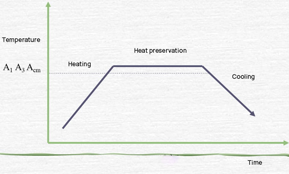
The process typically involves three main stages:
Different heat treatment processes, such as annealing, normalizing, quenching, and tempering, utilize variations of these stages to achieve specific results. For instance, quenching involves rapid cooling to increase hardness, while annealing uses slow cooling to improve ductility and reduce internal stresses.
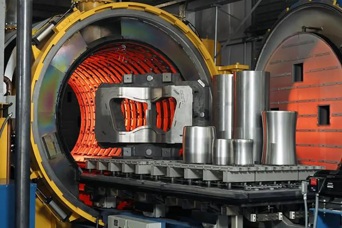
The effectiveness of heat treatment relies on several factors, including the metal’s chemical composition, initial microstructure, heating temperature, holding time, and cooling rate. Modern heat treatment processes often employ precise temperature control, protective atmospheres, and computer-controlled cooling systems to ensure consistent and optimal results.
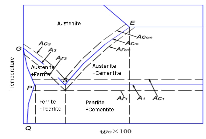
When steel is heated, it undergoes several critical phase transformations that significantly alter its microstructure and properties. These transformations are fundamental to heat treatment processes and greatly influence the final characteristics of the steel.
At room temperature, carbon steel typically exists in a ferrite-pearlite structure. As the temperature increases, the following transformations occur:
Understanding these transformations is crucial for optimizing heat treatment processes such as annealing, normalizing, quenching, and tempering. The heating rate, peak temperature, and holding time all play vital roles in controlling the final microstructure and properties of the steel.
Modern heat treatment often employs precise temperature control and specialized equipment like induction heaters or controlled atmosphere furnaces to achieve desired transformations while minimizing detrimental effects such as decarburization or excessive grain growth.
The C-curve, also known as the Time-Temperature-Transformation (TTT) diagram, is a critical tool in metallurgy used for analyzing the transformation of carbon steel’s microstructure during cooling after austenitization. This curve provides valuable insights into the kinetics of phase transformations and helps engineers optimize heat treatment processes to achieve desired mechanical properties.
There are two primary methods for cooling steel in the heat treatment process:
In practical industrial production, continuous cooling is the most commonly employed method due to its simplicity and efficiency. However, understanding both transformation processes is crucial for comprehensive steel heat treatment design and optimization.
The C-curve serves as a fundamental tool for predicting microstructural evolution and designing heat treatment cycles to achieve specific mechanical properties in carbon and low-alloy steels. It enables metallurgists and engineers to tailor the cooling process to obtain desired combinations of strength, hardness, and ductility in steel components.


Isothermal transformation curve of undercooled austenite in eutectoid steel

The austenite of eutectoid steel is cooled to a temperature ranging from A1 to 550°C, resulting in a pearlite structure through the process of isothermal transformation. This transformation of austenite into pearlite is a result of the alternating nucleation and growth of ferrite and cementite, as depicted in Figure 3-7.
Firstly, the nucleus of cementite crystals is formed on the grain boundary of austenite.
The carbon content of cementite is higher than that of austenite, leading to absorption of carbon atoms from the surrounding austenite.
As a result, the nearby austenite’s carbon content is reduced, creating conditions for the formation of ferrite and converting this part of austenite into ferrite.
The low carbon solubility of ferrite means that excess carbon must be transferred to adjacent austenite as it grows, causing the carbon content of the adjacent austenite region to increase and creating conditions for the formation of new cementite.
Through this process, austenite is eventually fully transformed into a pearlite structure with alternating layers of ferrite and cementite.

The formation of pearlite requires the movement of carbon atoms, with the distance of movement determining the width of the pearlite lamellae. At high temperatures, the movement of carbon atoms is more extensive, resulting in wider pearlite lamellae.
Conversely, at low temperatures, the carbon atoms have difficulty moving and therefore the pearlite lamellae are denser. The microstructure transformed from 727°C to 650°C is pearlite.
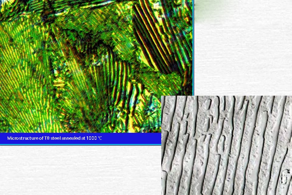
The structure obtained through transformation between 650°C and 600°C is known as sorbite, which is also referred to as fine pearlite. The transformation between 600°C and 550°C results in the formation of troostite, which is also known as very fine pearlite.

These three types of pearlite structures are only differentiated by their lamellar spacing and do not have any fundamental differences.
The products of the isothermal transformation of austenite in eutectoid steel, from undercooling to a temperature range of 550°C to 240°C, belong to the bainite structure. The upper bainite is formed in the upper part of this temperature range, while lower bainite is obtained in the lower part. The lower bainite has improved hardness and strength, as well as better plasticity and toughness. However, the upper bainite does not have any practical applications.

It is highly challenging for carbon atoms in austenite to shift below 240°C.
Austenite only undergoes an isomorphic transformation, changing from a face-centered cubic (y-iron) structure to a body-centered cubic (α-iron) structure.
All carbon atoms within the original austenite stay in the body-centered cubic lattice, resulting in a supersaturated α-iron.
This supersaturated solid solution of carbon in α-iron is referred to as martensite.
When eutectoid steel’s austenite is cooled down to 240°C (MS), it begins to transform into martensite.
As the temperature continues to drop, the amount of martensite increases while the undercooled austenite decreases.
By the time the temperature reaches -50°C (MF), the undercooled austenite has completely transformed into martensite.
Thus, the structure between MS and MF consists of martensite and retained austenite.
Due to variations in carbon content, martensite has two forms.
Martensite with a high carbon content takes on a needle-like shape, known as needle-like martensite.
Martensite with a low carbon content, on the other hand, is plate-like and referred to as plate-like martensite.

| Tissue | Carbon content (%) | Mechanical properties | |||
| HRC | (Mpa) | ak J/cm2 | Ψ(%) | ||
| Low carbon | 0.2 | 40~45 | 1500 | 60 | 20~30 |
| High carbon | 1.2 | 60~65 | 500 | 5 | 2~4 |
Table 4-5 comparison of properties of low carbon martensite 15MnVB steel and quenched and tempered 40Cr steel
| Steel grade | 15MnVB40Cr |
| State | Quenching and tempering state of low carbon martensite |
| HRC | 4338 |
| σo.2/MPa | 1133800 |
| σb/MPa | 13531000 |
| δ5(%) | 12.69 |
| φ(%) | 5145 |
| ak/Jcm-2 | 9560 |
| ak(-50℃)/J.cm-2 | 70≤40 |
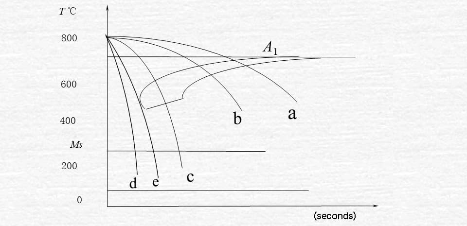
Fig. 3-9 cooling transformation curve of eutectoid steel
a. Cooling with furnace
When the cooling curve intersects with the start line for the pearlite transformation, the transformation of austenite to pearlite begins.
Once the cooling curve intersects with the end line of the transition, the transformation is complete.
As a result of the transformation occurring within the pearlite region, a pearlite structure is formed.
b. Cooling in air
As a result of the rapid cooling rate, the transformation takes place in the sorbite region, producing ferrite as the transformation product.
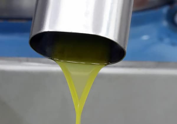
c. oil cooling
The cooling curve only intersects with the start line for the pearlite transformation (in the troostite transformation zone), but does not intersect with the end line.
As a result, only a portion of the austenite is transformed, resulting in the formation of troostite as the transformation product. The remaining portion of austenite transforms into martensite upon cooling to the MS line.
Finally, a mixed structure of martensite and troostite is obtained.
This refers to the product that has been cooled in oil.
d. Water cooling.
Due to the rapid cooling rate, the cooling curve does not intersect with the start line for the pearlite transformation.
When cooled below the start line for the martensite transformation, austenite will transform into martensite.
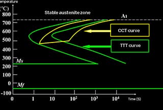
The continuous cooling curve is located to the lower right of the isothermal C curve, with a lower P transformation temperature and a longer duration.
Eutectoid and hypereutectoid steel have a P-transformation termination line, but no B-type transformation during continuous cooling.
For hypoeutectoid steel, subcooling in a specific temperature range during continuous cooling may result in partial transformation into B.
Determining the continuous cooling transformation curve is challenging, so many steels still lack this information.
In practical heat treatment, the continuous cooling transformation process is often estimated by referring to the C curve.
Comparison of TTT curve and CCT curve of eutectoid carbon steel

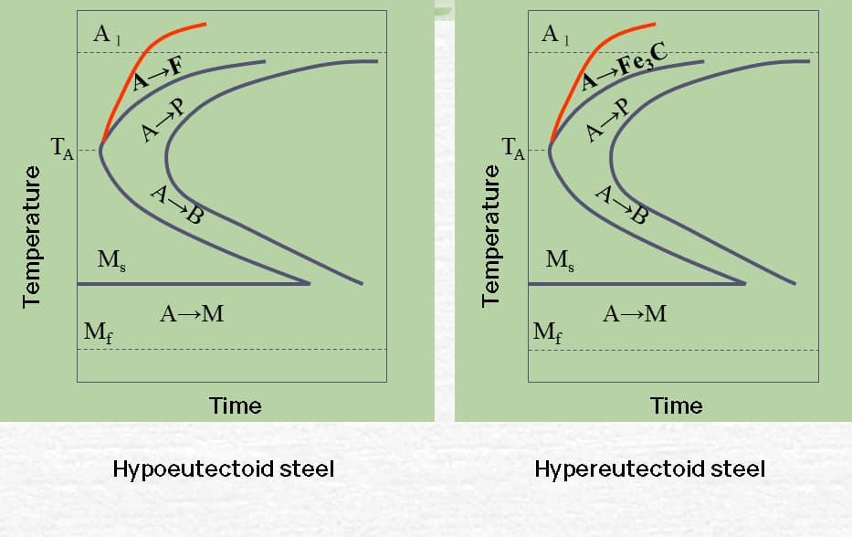
TT curve of hypoeutectoid and hypereutectoid steels
(1) Concept of hardenability
The hardness of steel refers to the depth to which the steel can be hardened during quenching, which is a characteristic of the steel.
During quenching, the cooling rate varies at different sections of the workpiece.
The surface cools at the fastest rate, surpassing the critical cooling rate for the formation of martensite. As a result, a martensitic structure is formed after quenching.
As the cooling rate decreases towards the center, if the cooling rate at a certain depth from the surface drops below the critical cooling rate required for the formation of martensite in the steel, then the workpiece will not fully harden as there will be a non-martensitic structure present after quenching.

(2) Effect of hardenability on mechanical properties
The mechanical properties of steels with good hardenability are uniform throughout the section, whereas those of steels with poor hardenability vary along the section. The mechanical properties, particularly toughness, decrease as you move closer to the center.

Fig. 5-53 comparison of mechanical properties of steels with different hardenability after quenching and tempering treatment
a) Hardened shaft
b) Unhardened shaft
(3) Determination and expression of hardenability
There are several methods to determine hardenability. The most widely used method, as specified in GB225, is the end quench test for structural steel. This test measures the thickness of the hardenable layer.
Another commonly used measure of hardenability is the critical diameter. This value represents the maximum diameter of the semi-martensitic structure (50%) that can be achieved at the center of the steel after quenching in a cooling medium. It is denoted as Do.


