How can we transform thin sheets of metal into strong, smooth-edged components? The answer lies in the fascinating process of hemming bending. This article explores four effective techniques, from flat bottom dies to hydraulic hemming tables, each suited for different materials and applications. Readers will learn how these methods not only enhance the strength and safety of metal products but also improve their aesthetic appeal. Dive in to discover which hemming bending solution best fits your manufacturing needs.
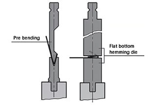
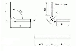
Hemming (flattening) bending is a frequent bending operation method that typically involves bending the edge of a workpiece into either parallel edges or rounded edges, as illustrated in Figure 1.

Fig. 1 Schematic diagram of hemming and bending
The objective of hemming and bending is to remove sharp edges, enhance the strength of the workpiece, and improve its appearance.
The process of flattening bending typically involves two steps:
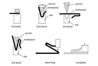
(1) Pre-bend the workpiece to 30°, and then flatten and bend the workpiece as shown in Figure 2.

Fig. 2 Steps of hemming and bending
To choose the right flattening bending solution, it is necessary to first consider the material and thickness of the workpiece and the frequency of flattening bending.
(2) It is important to note that the hemming die can also be used for regular bending when hemming is not required.
There are two types of hems:

The charts on the right show the necessary force to produce the two hemming types described above.
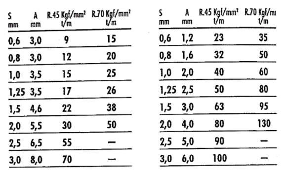
There are four primary hemming bending solutions designed to accommodate various bending conditions and material requirements in sheet metal fabrication:
(1) Flat bottom hemming die: This traditional solution provides a simple, cost-effective approach for creating straight hems. It’s ideal for thinner gauge materials and applications where high-volume production is required. The flat surface ensures consistent pressure distribution across the hem.
(2) U-shaped hemming die: Engineered for enhanced stability and precision, this die features a U-shaped channel that cradles the workpiece during the hemming process. It’s particularly effective for thicker materials or parts requiring tighter tolerances. The U-shape helps prevent material springback and ensures more uniform hem closure.
(3) Spring-type hemming die: This advanced solution incorporates spring-loaded components to provide adaptive pressure during the hemming operation. It’s excellent for materials with varying thicknesses or slight irregularities, as the springs compensate for these differences. This die type is often used in automotive panel production where consistent hem quality is crucial across complex geometries.
(4) Hydraulic hemming table: Offering the highest degree of control and versatility, hydraulic hemming tables use fluid pressure to create precise, adjustable hemming force. This solution is ideal for large panels, intricate shapes, or applications requiring frequent adjustments. The hydraulic system allows for fine-tuning of pressure and speed, enabling operators to optimize the hemming process for different materials and geometries.
Each of these hemming solutions offers unique advantages, and the choice depends on factors such as material properties, part geometry, production volume, and quality requirements. Modern manufacturing often employs a combination of these techniques to achieve optimal results across diverse product lines.
Related: V & U-shaped Bend Force Calculator
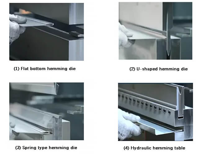
Fig. 3 Four hemming and bending solutions
The flat bottom hemming die accomplishes hemming and bending through the use of two sets of dies, that is, one set of upper and lower standard dies and one set of upper and lower flat bottom dies are employed together, as depicted in Figure 4.

Fig. 4 Schematic diagram of flat bottom hemming die
The process begins with pre-bending the workpiece to 30° using a standard die.
Next, the workpiece is flattened and bent on the flat bottom die.
Since the flat bottom hemming die requires a two-step bending process, it is mainly suitable for working conditions where hemming and bending are infrequent and offer cost-effectiveness.
However, there is some lateral force during hemming, and the maximum thickness of the flattened carbon steel plate is limited to 2 mm.
To address the limited thickness in flattened bending, a ball-type movable flat bottom lower die was innovatively introduced. The maximum thickness of the flattened carbon steel plate or stainless steel plate can now reach 4 mm, as demonstrated in Figure 5.

Fig. 5 Schematic diagram of ball type movable lower die
A set of U-shaped hemming dies can be used for pre-bending and flattening, as depicted in Figure 6.

Fig. 6 Schematic diagram of U-shaped hemming die
The benefit of the U-shaped hemming die is its versatility; when it is not required for hemming and bending, it can be utilized for standard air bending, offering high utilization and cost-effectiveness.
The maximum thickness for a flattened carbon steel plate is 1.5 mm, while the maximum thickness for a flattened stainless steel plate is 1 mm. The minimum flange size that can be flattened is approximately 14 mm.
The spring hemming die comprises a 28° standard upper die and a 30° hemming lower die. The hemming insert of the lower die is supported by a spring.
During the hemming process, the pre-bent workpiece is placed between the hemming insert and the guide insert of the hemming lower die. The hemming insert follows the descent of the upper die and presses down until the pre-bent workpiece is flattened.
The maximum thickness that the spring hemming die can flatten in a carbon steel plate is 2 mm.
Like the other hemming solutions, the spring hemming die can also be used for standard air bending when not used for hemming bending.
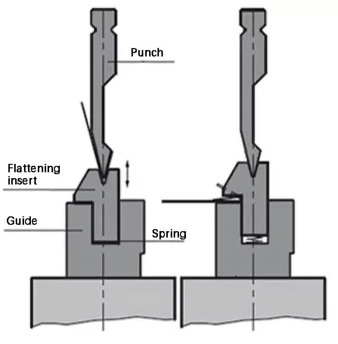
Fig. 7 Schematic diagram of spring hemming die
The hydraulic hemming table (as depicted in Figure 8) operates similarly to the spring hemming die, but instead of a spring, a hydraulic cylinder is used to control the lift of the hemming insert.
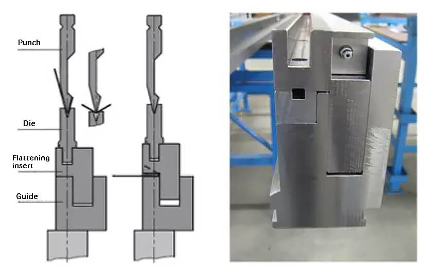
Fig. 8 Schematic diagram of hydraulic hemming workbench
The oil pressure is 100 bar, which makes it possible to bend thicker and heavier workpieces. To further enhance the service life of the hydraulic hemming table, a hardening hemming insert can be added.
The standard lower die can be placed on the hydraulic hemming workbench and the V opening can be selected according to your needs, up to a maximum of 40 mm. The lower die can be clamped manually or automatically for more efficient die changes.
The hydraulic hemming table is capable of flattening carbon steel plates with a thickness of up to 3 mm. The spring hemming die or hydraulic hemming table can be clamped onto the fixture or mechanical compensation table.
The hydraulic hemming table can also be directly installed on the lower beam of the bending machine, which provides greater opening height and flexibility.
In conclusion, the four different hemming and bending solutions each have their own unique advantages. Depending on the hemming and bending application scenario, you can choose the appropriate solution.


