How does the precision of a press brake impact the quality of metal bending? This article explores the critical link between the manufacturing accuracy of press brakes and the resulting bending precision. By analyzing factors such as worktable flatness and slider stroke, it reveals how even small deviations can lead to significant bending errors. Readers will understand the importance of precise machinery in ensuring high-quality bends, reducing errors, and improving overall efficiency in metalworking processes.
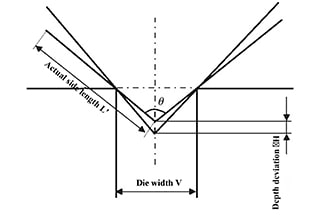
The sheet metal bending machine is a commonly used sheet metal processing equipment that uses a simple universal bending die to bend complex parts. Equipped with the necessary processing equipment, it can also perform processes such as grooving, shallow drawing, punching, and voltage ripple.
This machine is known for its simple die, versatility, ease of adjustment and replacement, and ability to perform various sheet metal forming processes.
As part of modern manufacturing technology, the development and research of precision machinery manufacturing technology is highly valued by developed countries for its impact on the economy. The advancement of precision and ultra-precision machining technology has improved the accuracy and technical level of the entire machinery manufacturing industry, leading to improved quality, performance, and competitiveness of mechanical products.
The increasing demand for accuracy in related industries has made improving the accuracy of bending an urgent issue in the research and development of bending machines. The accuracy of a press brake machine is the primary factor in determining the quality of the bend.
Sheet metal processing errors can negatively impact subsequent assembly, increase the need for trial die repair and shape correction, prolong product development cycles, and limit the advancement and application of incremental bending forming, especially for large workpieces made of high strength and high springback steel plates.
Therefore, it is crucial to analyze the mechanism of processing errors in sheet metal bending machines, identify the main factors affecting processing accuracy, and propose effective methods and measures to improve the accuracy of bending machines. This will improve the competitiveness and added value of the sheet metal bending machine in the market.
In this article, the PBH110-3100 CNC sheet metal bending machine is used as the research subject. The theory of elastic mechanics is used to establish the analysis model of bending error and to analyze the impact of machine tool manufacturing accuracy on metal sheet bending accuracy.
According to the national standard GB/T 14349-93, the inspection of the bending machine’s working accuracy consists of two main components: bending angle and straightness, as outlined in Table 1.
Requirements for test pieces during working accuracy inspection:
1) Length of specimen:
2) The width of the specimen shall not be less than 100 mm.
3) Thickness of specimen:
4) The material of the test piece is A3 steel plate, and its tensile strength σb ≤ 450 MPa.
Table 1 Bending accuracy inspection diagram of sheet metal bending machine
| Inspection items | Diagram | Tolerance | Inspection tools | Inspection methods | |
|---|---|---|---|---|---|
| Bending angle of specimen |  | Accuracy classification | On the whole length | Universal angle meter | The universal angle ruler shall be placed on the outer surface of the bending test piece and measure it several times (at least three places per M). The error is calculated by the difference between the maximum and minimum angle of the angle ruler and the specified bending angle of 90°. |
| I | ± 30′ | ||||
| II | ± 1° | ||||
| III | ± 1°30′ | ||||
| Bending straightness of specimen |  | Accuracy classification | On the whole length | Feeler gauge inspection level ruler | Place the inspection surface of a 1000 gauge against the edge of the bending specimen, and measure the gap between them with a feeler gauge. The error is calculated by the maximum reading value within any 1 m length. |
| I | 0.30 | ||||
| II | 0.75 | ||||
| III | 1.00 | ||||
When there is flatness error along the length of the worktable, it impacts the depth at which the upper die tool enters the lower die notch, causing a deviation ΔH equal to the longitudinal flatness error (a) of the worktable.
Figure 1 shows the impact of worktable flatness (longitudinal) on bending angle error.
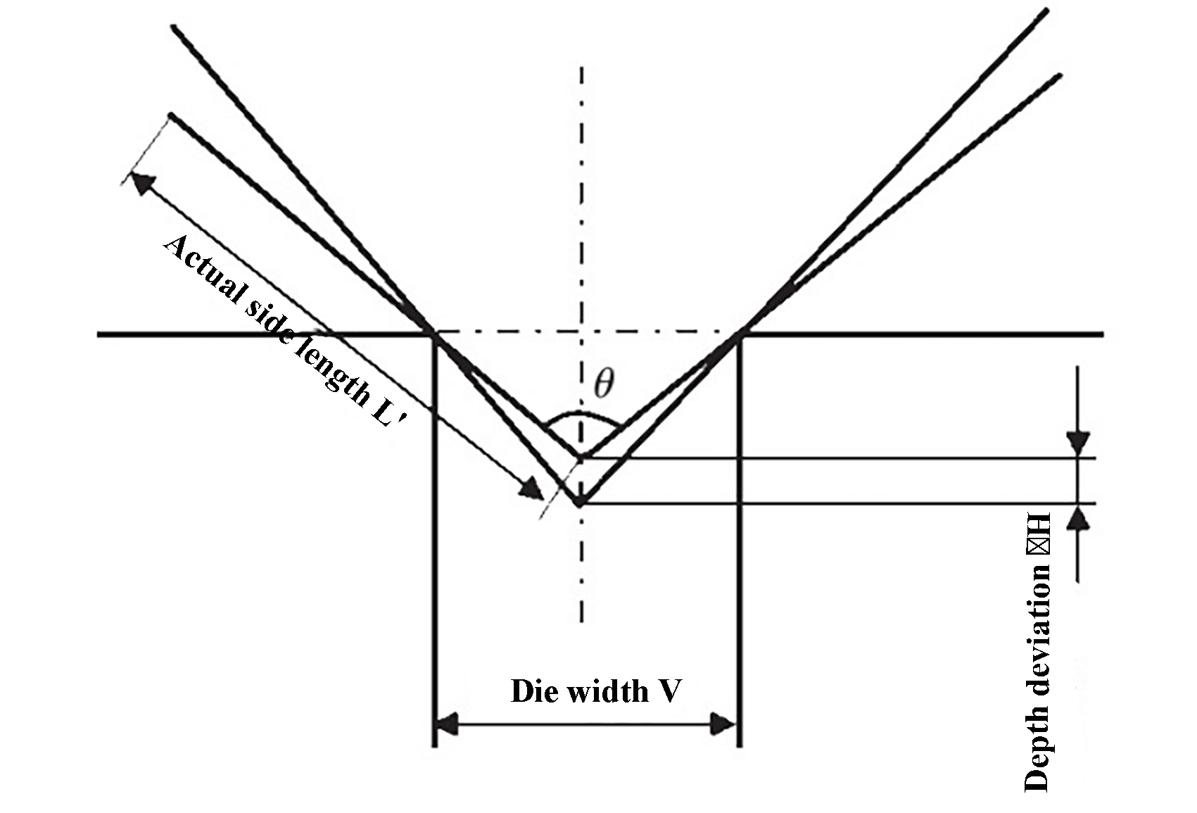
Fig. 1 Effect of flatness error of worktable on bending angle error.
The depth deviation △H of the upper die tool entering the lower die notch is:

The bending angle of the workpiece is:

Then the angle deviation of the bending workpiece is:

When the worktable has flatness error, the influence of flatness error on the straightness error of bending workpiece is shown in Figure 2.

Fig. 2 Effect of flatness error of worktable on bending straightness error.
The straightness error of the bending workpiece is equal to the longitudinal flatness error.
That is:

The plane error of worktable has no influence on the accuracy of sideline.
The influence of horizontal flatness of worktable on bending accuracy is similar to that of vertical flatness.
The bending angle error of the workpiece is:

The bending straightness error of the workpiece is:

The horizontal flatness of worktable has no influence on the accuracy of bending sideline length.
The influence of slider stroke on perpendicularity of the working face and bending accuracy is shown in Figure 3.
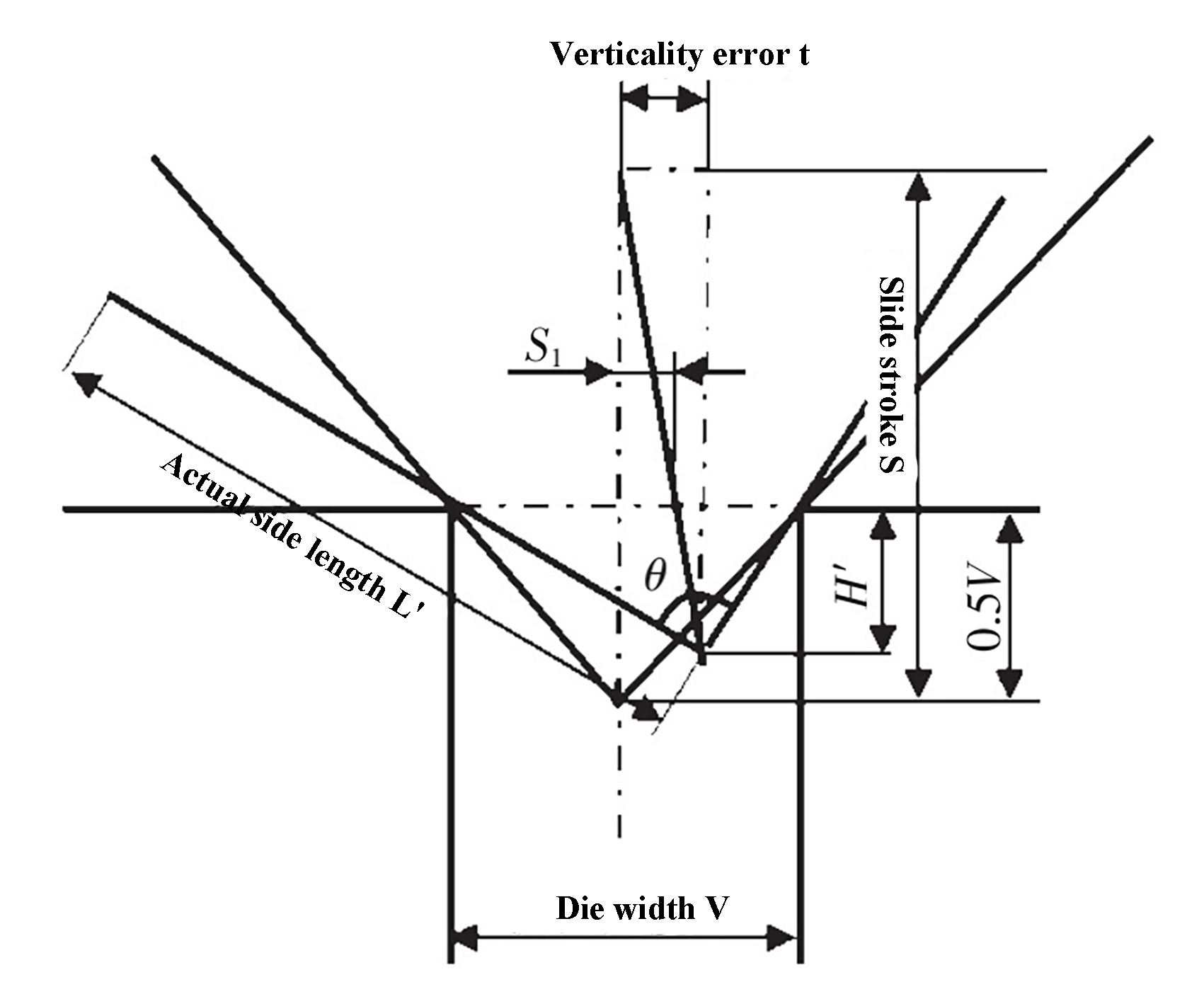
Fig. 3 Influence of slider stroke on perpendicularity of working face and bending accuracy.
When the perpendicularity deviation of the slider stroke to the worktable is t, the depth H ‘of the slider into the die is:

The bending angle of the bending workpiece is:

The bending angle error of the bending workpiece is:

When the perpendicularity deviation of the slider stroke to the worktable is t, the straightness error of the bending workpiece is:

When the perpendicularity deviation of the slider stroke to the worktable is t, the distance S1 from the bending center line of the upper die is:

It can be found that:

The actual bending edge length L ‘is:

The length error of bending sideline is:

Table 2 displays the impact of various factors of manufacturing accuracy of the PBH110-3100 CNC sheet metal bending machine on the bending accuracy of the workpiece.
Table 2 Analysis of the influence of various factors on bending accuracy
| Parameters | Bending force | 1100 kN | Slide thickness | 60 mm | Slide stroke | 220 mm | |
|---|---|---|---|---|---|---|---|
| Worktable length | 3100 mm | Worktable height | 890 mm | Plate thickness | 5 mm | ||
| 2660 mm | Worktable thickness | 60 mm | Die width | 40 mm | |||
| Slide height | 1300 mm | Deflection calculation
Correction | 1.5 mm | Upper die height | 120 mm | ||
| Classification | Project | Deviation | Influence on bending accuracy | ||||
| Tolerance | Actual value | Straightness error △θ | Angle deviation
△l | Side length error
△L | |||
| Machine tool manufacturing accuracy | Flatness of worktable | Longitudinal (a) | 0.08 | 0.06 | 0.172 | 0.06 | × |
| Horizontal (b) | 0.03 | 0.02 | 0.057 | 0.02 | × | ||
| Perpendicularity of slider stroke to working face | 0.25 | 0.2 | -0.003 | 0.000 | 0.182 | ||
The analysis table shows that the deviation in bending angle is about three times that of the worktable flatness. The national standard has low requirements for the flatness of the upper die mounting surface, resulting in large bending angle errors. Bending machine manufacturers can improve the flatness of the worktable to meet production needs.
However, the slider stroke has little impact on the perpendicularity of the working face and its effect on the bending angle. The flatness of the worktable directly affects the straightness deviation in bending, with the straightness error being less impacted by the slider stroke on the perpendicularity of the working face.

