Choosing the right CNC machine can be daunting, given the array of models, systems, and specifications. This article simplifies the process, breaking down the selection into four key aspects: model selection, CNC system choice, precision requirements, and main specifications. Whether you’re a seasoned machinist or a beginner, you’ll learn how to assess your needs and make an informed decision, ensuring optimal performance and cost-efficiency. Dive in to find out how to navigate the complexities and pick the perfect CNC machine for your operations.
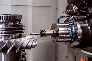
The CNC machine is widely utilized for its high precision, reliability, efficiency, and capability to machine complex curved workpieces.

However, if the selection is not appropriate, it will not be able to achieve its full potential and most machining centers come with a high price tag, which can result in significant cost pressure.
The general selection process includes choosing the model, selecting the CNC system, determining the accuracy of the machine tool, and specifying the main features.
Of these, the selection of the model and the CNC system are the riskiest, while the precision of the machine and main specifications are the second priority.

Therefore, to minimize the risk of selection, we can start by considering the following four aspects:
Under the condition of fulfilling the processing needs, the simpler the equipment, the lower the risk.
Both turning machining centers and CNC lathes can process shaft parts, but a turning center that meets the same processing specifications is significantly more expensive compared to a CNC lathe.
If there are no additional technical requirements, the risk of choosing a CNC lathe is undoubtedly low.
Additionally, when choosing an economical and ordinary CNC lathe, opt for a more cost-effective option.

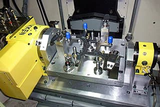
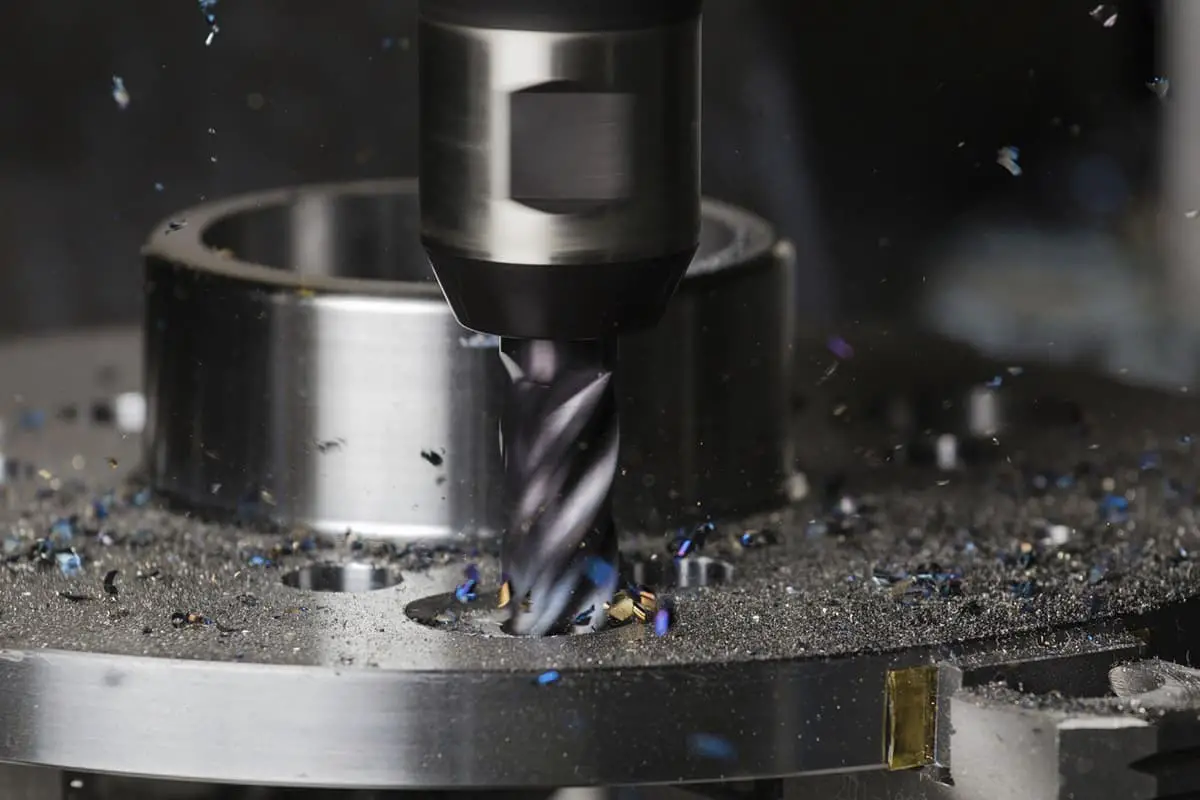
In the processing of boxes, cavities, and mold parts, CNC milling machines and machining centers with the same specifications can meet the basic processing requirements, but there is a difference in price of about half (excluding the cost of air source, tool changer, and other supporting costs).
Therefore, in mold processing, it is only necessary to choose a machining center if the tool needs to be changed frequently.
For extended periods of milling with a fixed cutter, a CNC milling machine should be selected.
Currently, many machining centers are being used as CNC milling machines.
Parts that can be processed by CNC lathes can often be processed by conventional lathes, but parts that can be machined by CNC milling machines cannot be processed by most conventional milling machines.
Therefore, in integrated machining enterprises that handle shaft parts, box parts, and cavity parts, CNC milling machines should be the preferred choice.

When purchasing a CNC machining center, the same machine can be equipped with various CNC systems.
The performance of these systems varies greatly and has a direct impact on the equipment’s price.
Currently, the types and specifications of CNC systems are abundant.
The imported systems mainly include FANUC from Japan, SINUMERIK from Germany, MITSUBISHI from Japan, NUM from France, FIDIA from Italy, FAGOR from Spain, and A-B from the USA, among others.

Each company offers a range of products with varying specifications.
The basic principle for reducing the risk of selecting a CNC system is to consider the performance-price ratio, ease of use and maintenance, and the system’s service life.
Therefore, we should not blindly pursue high-level, new systems.
The selection should be based on the machine’s main performance and a comprehensive analysis of the system’s performance and price should be conducted before making a decision.
At the same time, it is advisable to avoid choosing CNC systems with a traditional closed architecture or systems that have a PC embedded in the NC structure. This is because the expansion, modification, and maintenance of such systems must be performed by the system supplier.

Therefore, it is advisable to select an open CNC system with an NC embedded PC structure or a SOFT structure as much as possible.
The CNC software for this type of system is installed on the computer and the hardware component is only a standardized universal interface between the computer and the servo drive and external I/O.
Just as a computer can install various brands of sound cards, graphics cards, and corresponding drivers, users can use the open CNC kernel to develop the required functions on the WINDOWS NT platform and create various types of CNC systems.
In addition to the basic functions of the CNC system, there are many options available.
Users can choose some functions based on their own processing requirements, measurement needs, programming needs, etc. and include these functions in the order contract. In particular, the DNC function for real-time transmission should be considered.

Generally, there are 20 to 30 precision inspection items for CNC machining centers, but the most distinctive items are: single-axis positioning accuracy, single-axis repeat positioning accuracy, and the roundness of the test piece produced by simultaneous machining of two axes.
The positioning accuracy and repeat positioning accuracy comprehensively indicate the overall precision of each moving part of the axis.
The single-axis positioning accuracy refers to the error range when positioning at any point within the axis’ stroke, which directly reflects the machine tool’s machining accuracy.
The repeat positioning accuracy reflects the stability of the axis’ positioning at any point within the stroke, and is a basic indicator of the axis’ ability to work stably and reliably.
Among these two indicators, repeat positioning accuracy is particularly important.
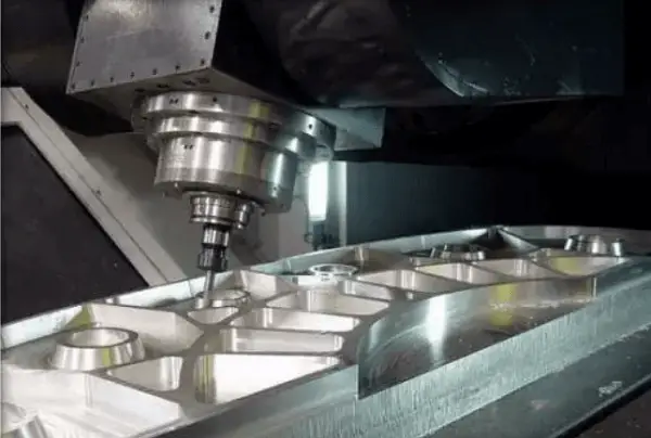
Precision aluminum alloy shell processing
Currently, the software in the numerical control system has a robust error compensation function, which can compensate for the systematic errors of each link in the feed transmission chain.
For example, the pitch error and cumulative error of the lead screw can be compensated using the pitch compensation function, and the reverse dead zone in the feed chain can be eliminated through reverse backlash compensation.
However, the error compensation function in electronic control cannot compensate for random errors (such as gaps caused by changes in gaps, elastic deformation, and contact stiffness of various links in the drive chain).
These often reflect different movement loss due to factors such as the load size of the workbench, the length of the moving distance, and the speed of the moving positioning speed.
In some open-loop and semi-closed-loop feed servo systems, the mechanical drive components after the measurement component are influenced by various accidental factors and have substantial random error effects.
For example, the actual positioning position of the worktable may drift due to the thermal elongation of the ball screw.
Therefore, the appropriate choice of repeat positioning accuracy can greatly reduce the risk of precision selection.
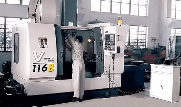
The precision of milling cylindrical surfaces or milling space spiral grooves (threads) is a comprehensive evaluation of the machine’s CNC axis (two-axis or three-axis) servo following performance and the numerical control system’s interpolation function.
The evaluation is done by measuring the roundness of the cylindrical surface.
In the cutting trial using a CNC milling machine, there is also four-sided square milling, which is another method to judge the accuracy of the two controllable axes in linear interpolation motion.
For CNC milling machines, the roundness of the cutting pieces processed by two or more axes cannot be disregarded.
For machines with higher positioning accuracy, it is also important to consider whether the feed servo system is in a semi-closed loop or full closed loop mode and the accuracy and stability of the detection components.
If the machine tool adopts a semi-closed-loop servo drive mode, its accuracy stability is affected by external factors.
For example, changes in working temperature can cause the ball screw in the transmission chain to elongate, leading to drift in the actual positioning position of the worktable and affecting the machining accuracy of the workpiece.

The main feature specifications of the CNC machining center should be selected based on the determined range of typical workpiece machining dimensions.
The main specifications of the CNC machining center are the stroke range of several CNC axes and the power of the spindle motor.
The three basic linear coordinates (X, Y, Z) strokes of the machine tool reflect the machining space available to the machine.
The two coordinates X and Z in the lathe reflect the size of the permissible rotor.
In general, the contour size of the machined part should be within the machining space of the machine tool.
For example, if a typical workpiece is a box with dimensions of 450 mm × 450 mm × 450 mm, then a machining center with a working surface size of 500 mm × 500 mm should be selected.
Choosing a work surface that is slightly larger than a typical workpiece takes into account the space needed for installing the clamp.
The machine tool table size and the three linear coordinate strokes have a proportional relationship.
For example, for the above machine tool with a table size of 500 mm × 500 mm, the X-axis stroke is generally 700800 mm, the Y-axis is 500700 mm, and the Z-axis is 500~600 mm.
Therefore, the size of the work surface largely determines the size of the processing space.
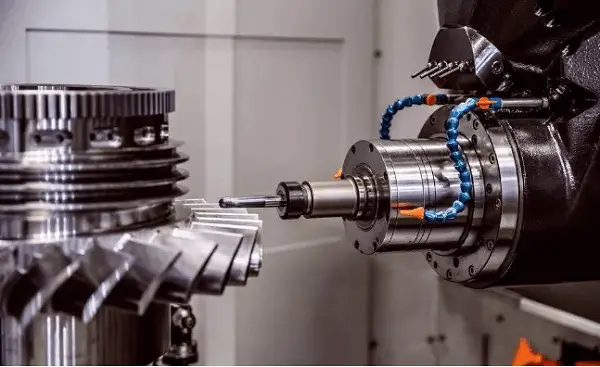
In some cases, the size of the workpiece may be larger than the coordinate stroke of the machining center. In such instances, it is crucial to ensure that the machining area on the part is within the range of the stroke. Several factors must be taken into consideration, including the allowable bearing capacity of the machine table, potential interference with the machine tool change space, and potential interference with machine accessories such as guard covers.
CNC machining centers can have a variety of different motor configurations, even within the same type of machine. The cutting rigidity and high-speed performance of the spindle are typically an indicator of the machine tool’s overall performance.
It is worth noting that the spindle motor power of lighter machine tools may be 1-2 levels less powerful compared to standard machine tools. Currently, the spindle speed of a general machining center ranges from 4000 to 8000 r/min, while high-speed vertical machine tools can reach speeds of 20,000 to 70,000 r/min and horizontal machine tools can reach speeds of 10,000 to 20,000 r/min. Additionally, the power of the spindle motor is doubled in these high-speed machine tools.
The power of the spindle motor is a reflection of the machine tool’s cutting efficiency and cutting rigidity, as well as an indicator of the overall rigidity of the machine.

In modern small and medium-sized CNC machining centers, the mechanical shifting of the spindle box is used less frequently. Instead, a DC or AC adjustable speed motor with a high power is often used to directly connect to the spindle or even in an electric spindle structure.
However, this structure has limitations in terms of torque during low-speed cutting. This is because the output power of the speed-regulating motor decreases at low speeds. To ensure adequate torque at low speeds, a high-power motor must be used.
As a result, the spindle motor of CNC machining centers with the same specifications is several times larger than those in ordinary machine tools.
See also:
It is important to check the low-speed output torque of the machine when a large amount of low-speed machining is required on a typical workpiece.

