Choosing the right hydraulic press brake can be challenging due to the variety of options available. Understanding the distinctions between NC and CNC models is crucial. This guide explains key factors like accuracy, efficiency, and operator experience, helping you select the most suitable press brake for your specific needs. Whether you need precision or budget-friendly options, this article provides insights to make an informed decision.
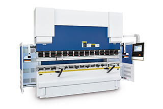
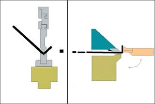
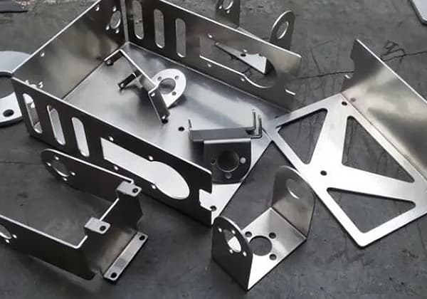
A press brake is a machine that uses a punch and die (either general or specialized) to bend cold metal plates into workpieces with various geometric shapes.
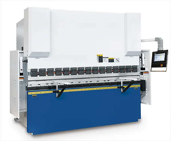
Typically, a press brake employs a specialized CNC system for the bending machine.
The coordinate axis of press brake machines has evolved from a single axis to as many as twelve axes, which are classified based on their functions as follows:
Related reading: Press Brake Axis Explained
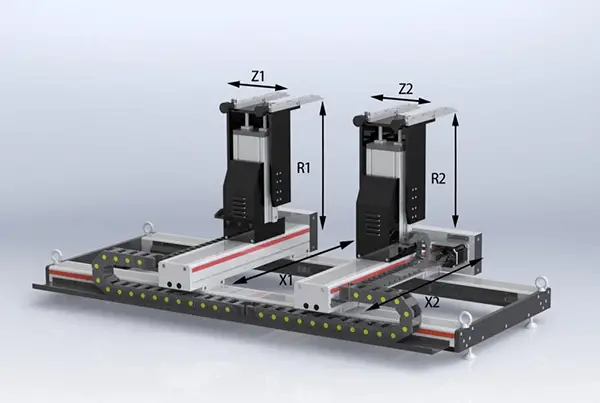
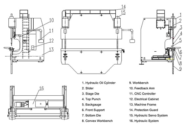
The numerical control system can automatically control the depth of the ram operation, adjust the left and right tilt of the ram, adjust the front and rear and left and right positions of the rear stopper, control the pressure tonnage, and adjust the speed of the ram approach.
Related reading: Press Brake Bending Depth Calculator
The hydraulic press brake can effortlessly perform actions such as the downward movement of the ram, inching, continuous pressure, return, and midway stop. It can also complete multiple bendings at the same or different angles at once.
Ram:
The ram component typically uses hydraulic transmission. It consists of a ram, oil cylinder, and a mechanical stop fine-tuning structure. The numerical control system controls and adjusts the value of the mechanical stop.
Synchronous System:
The synchronous system primarily uses a mechanical design and has a simple structure with stable and reliable performance. Its key components include a torsion shaft, swing arm, and joint bearing.
Workbench Section:
The workbench section is controlled by a button box and the moving distance is regulated by the numerical control system. It also has travel switch limit devices installed at the front and rear positions.
Backgauge Mechanism:
The backgauge mechanism is typically driven by a motor and its movement is mainly controlled by the NC system.
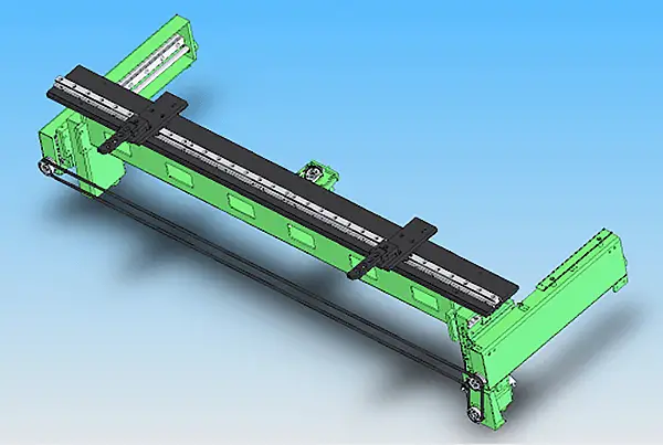
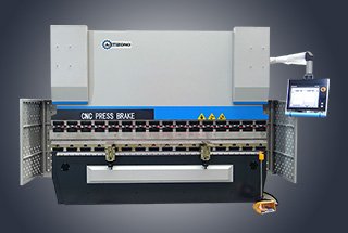
Press brake refers primarily to a plate bending machine, which is used for bending and shaping various metal plates.
This equipment is commonly used for sheet bending and is considered a large machine.
The selection of the press brake should be based on factors such as the intended use, working environment, degree of bending required, plate thickness, and other relevant conditions. Understanding how to properly select the right type is crucial knowledge.
Press brakes can be classified into different categories based on their working characteristics and modes.
The following is a comprehensive and in-depth introduction to the classification of press brakes:
There are several types of press brakes, which can generally be divided into manual press brakes, hydraulic press brakes, and NC/CNC press brakes.

Manual press brakes come in two forms: mechanical manual press brakes and electric manual press brakes.
These types of press brakes are popular both domestically and internationally due to their compact size, low energy consumption, high efficiency, large and fast production capabilities, wide range of applications, and ease of transportation.
The structure of manual press brakes is relatively simple and requires manual labor for operation. They are suitable for the processing and manufacture of small workpieces.

Hydraulic press brakes can be classified into different categories based on their synchronization modes, including torsional shaft synchronous press brakes, mechanical-hydraulic synchronous press brakes, and electro-hydraulic synchronous press brakes.
Based on the movement mode, hydraulic press brakes can further be divided into upward-moving press brakes and downward-moving press brakes.
Hydraulic press brakes are widely used in the sheet metal industry for applications such as automobiles, doors and windows, steel structures, and V-groove for sheet metal, among others.
The following are the key features and characteristics of hydraulic press brakes:

The core of the NC/CNC press brake is the press brake tool used for bending sheets. The tool consists of a support, workbench, and clamping plate.
The pressing plate generates force by energizing the coil, thereby clamping the sheet between the pressing plate and the base.
As the clamping method is based on electromagnetic force, the pressing plate can be customized according to specific workpiece requirements, making the operation simple and capable of processing workpieces with side walls.
NC/CNC press brakes are modern, large-scale machines known for their high precision and favored by many.
They offer flexible operation modes and can be linked with two press brake machines to handle long plate processing or operated as a single machine to improve utilization, reduce energy consumption, and automatically adjust compensation through the CNC system for convenience.
There are various models of NC/CNC press brakes, such as G-type, F-type, WC67k type, etc.
Different types of press brakes have unique performance and application fields, so it is essential to choose the appropriate machinery based on the use situation and operating environment to achieve optimal performance.
Related reading: Types of Press Brake Bending
What is the difference between torsion shaft synchronous press brakes and electro-hydraulic synchronous press brakes (in reference to NC press brakes and CNC press brakes)?
There are numerous press brakes available in the market today, with a wide range of installed configurations and systems.
Torsion shaft press brakes and electro-hydraulic press brakes are often compared due to their similar functions, but different strengths in terms of accessories, systems, and pricing.
So, how does one choose a high-performing, cost-effective, and user-friendly press brake from the many options available?
In the following sections, we will compare NC press brakes and CNC press brakes from multiple perspectives.
The design principles of the two models are distinct, leading to different structures that ensure synchronization on both sides of the bending ram.
The NC press brake uses a torsion axis to connect the left and right swing rods, forming a torsional axis forced synchronization mechanism that drives the oil cylinders on both sides to move up and down.
As a result, the NC press brake uses a mechanical forced synchronization mode, and the parallelism of the ram cannot be automatically monitored or adjusted.

Proofread the following content and output the proofread content:
“
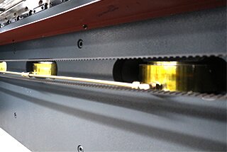
The CNC press brake is to install a grating ruler on the ram or bed.
The CNC system can analyze the synchronization on both sides of the ram through the information fed back by the grating ruler at any time.
“

In the event of an error, the CNC system will make adjustments through the proportional electro-hydraulic servo valve to synchronize the stroke on both sides of the ram.
The numerical control system, hydraulic control valve group, and grating ruler form the feedback closed-loop control system of the CNC press brake.
The parallelism of the ram determines the angle of the workpiece.
The NC press brake maintains the synchronization of the ram through mechanical means, lacking real-time error feedback and the ability to make automatic corrections, leading to subpar machining accuracy.
Furthermore, it has limited load-bearing capacity, as the NC press brake forces the synchronization mechanism to move the oil cylinders on both sides up and down through the torsion shaft, which may deform over time with partial loads.
On the other hand, the CNC press brake controls the ram synchronization through a proportional electro-hydraulic valve group and receives real-time error feedback from the grating ruler. In the event of an error, the system adjusts through the proportional valve to maintain the synchronization of the ram and improve machining accuracy.
During the operation of the machine, three points determine its running speed:
(1) Ram speed
(2) Rear stop speed
(3) Bending steps
The 6:1 or 8:1 oil cylinder is selected for the NC press brake, which is slow, while the 13:1 or 15:1 oil cylinder is selected for the CNC press brake, which is fast.
As a result, the fast down and return speeds of the CNC press brake are significantly higher than those of the NC press brake.
When the ram of the NC press brake moves down, it has the functions of rapid descent and slow descent, but the fast descent and return speeds are only 80mm/s, and the speed transitions are not smooth. The rear stopper operates at a speed of only 100mm/s.
In contrast, the ram of the CNC press brake has the functions of rapid descent and slow descent, with fast descent and return speeds reaching 200mm/s, and smooth speed transitions, greatly improving production efficiency. The rear stopper operates at a speed of 400mm/s.
Due to its design, the NC press brake is unable to bend under eccentric loads. Prolonged bending under eccentric loads will result in deformation of the torsion shaft.
However, the CNC press brake does not have this issue. The Y1 and Y2 axes on the left and right sides operate independently, allowing it to bend under partial loads.
Most NC press brakes do not have a CNC system and lack v-axis compensation.
As a result, when processing based on drawings, it is necessary to rely on the experience of veteran workers to make trial bends. If the results do not meet standards, additional trials are necessary, resulting in waste and a limited pool of potential operators with high salaries.
While it is possible to add a manual crowning system, the CNC press brake is controlled by a professional CNC system with v-axis compensation, making it easier to operate and requiring less experience from the operator.
The CNC press brake can simulate bending without the need for trial bends, simply requiring the correction of the drawings, inputting the steps and sizes, and proceeding with the bend directly.
The more control axes a NC press brake has, the less effective it becomes. Typically, it only controls the X-axis and Y-axis.
In contrast, the number of control axes for a CNC press brake is not limited. It can be 3 + 1 axis or more, with automatic program design capable of meeting high requirements, such as 4 + 1 axis, 5 + 1 axis, 6 + 1 axis, 7 + 1 axis, 8 + 1 axis, and so on.
The NC press brake can be improved with the addition of better components, such as a quick-release clamp, manual crowning, lifting stop fingers, ball screws, linear guide rail rear stop, oil cooler, and light curtain protection.

In contrast, the CNC press brake not only has these basic components, but can also be equipped with a variety of high-quality accessories.
For instance, it can have a Tyokko-type or Amada-type quick-release clamp in place of a standard one. The lifting stop fingers can be operated manually or electrically through an AC motor on the guide rail. The light curtain protection can be replaced by a more sensitive laser protection system.
The CNC press brake can also be fitted with a servo pump control system for energy savings, low noise, faster stamping speed, and lower fuel consumption, as well as a manipulator to improve production efficiency, a hydraulic clamping system, a follow-up supporter, and a laser angle detector.
The main difference between CNC and NC press brakes lies in the existence of a feedback closed loop and CNC crowning system.
See also:
The distinction between the two should be clear. The NC press brake adjusts the cylinder stroke mechanically, while the CNC press brake controls the stroke using hydraulic pressure. The NC press brake is controlled by a balance shaft, while the CNC press brake is synchronized by servo proportional valves on both sides.
The CNC press brake combines the benefits of electrical and hydraulic systems, offering high control precision, fast response speed, large output power, flexible signal processing, and the ability to easily monitor various parameters. One CNC press brake can have the same working efficiency as two to three NC press brakes.
Ram Left and Right Synchronization
The CNC system ensures precise and dynamic synchronization of the ram’s left and right sides. It incorporates advanced tilt detection and real-time correction algorithms, maintaining parallelism throughout the bending process and enhancing overall accuracy.
Bend Angle (Depth) Calculation
Utilizing sophisticated algorithms, the CNC system automatically computes the optimal bending depth. This calculation integrates multiple parameters including die angle, opening width, bend radius (R size), and sheet metal thickness, ensuring precise and consistent bending results across various material specifications.
Bending Depth Feedback
High-precision grating rulers, sourced from industry-leading manufacturers, provide real-time position feedback for both sides of the ram. The system employs advanced throat deformation compensation techniques, dynamically adjusting for machine deflection to maintain angle consistency across the entire workpiece length.
Worktable Deflection Compensation
The CNC system incorporates a predictive model to calculate and apply the necessary pressure for counteracting worktable deflection during bending. This proactive approach ensures uniform angles along the full length of the workpiece and significantly improves overall straightness and dimensional accuracy.
Angle Correction Mechanism
In cases where discrepancies arise between programmed and actual forming angles, the system offers a user-friendly interface for inputting error values. It then employs adaptive algorithms to automatically compensate and correct subsequent bends, ensuring consistent quality throughout the production run.
Precision Stop Positioning
Leveraging its integrated kinematic model, the system accurately calculates the optimal position for each stop axis based on the programmed bending height. It allows for rapid step changes and easy corrections, maximizing productivity while maintaining high precision.
Versatile Programming Modes
The system offers both intuitive graphical and detailed data programming interfaces. This dual approach facilitates rapid program creation, modification, and optimization, catering to operators with varying levels of expertise and programming preferences.
Expansion Length Calculation
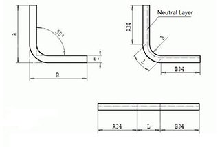
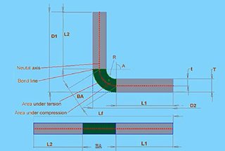
Utilizing advanced unfolding algorithms, the CNC system precisely calculates the required flat pattern length based on either graphical programming input or specified external/internal dimensions. This feature minimizes material waste and ensures accurate blank sizing.
Intelligent Interference Detection
The CNC system employs sophisticated collision avoidance algorithms to automatically determine the optimal bending sequence. By analyzing the programmed part geometry, tooling configurations, and machine constraints, it proactively identifies potential interferences. The system alerts operators to conflicts and offers the flexibility for manual process adjustments when needed.
In conclusion, selecting the optimal press brake hinges on specific processing requirements and operational constraints.
CNC (Computer Numerical Control) press brakes offer superior precision, real-time error compensation, and enhanced resistance to off-center loading on the bending ram. These machines utilize advanced servo-hydraulic systems and sophisticated control algorithms to maintain consistent bend angles and minimize springback. Conversely, NC (Numerical Control) press brakes, while less precise, provide adequate performance for less demanding applications. They lack real-time feedback mechanisms and exhibit reduced resistance to deflection loads, potentially affecting bend accuracy in complex parts.
Key factors to consider when making your decision include:

