Have you ever wondered how to weld two of the most challenging metals, copper and stainless steel, together? This article breaks down the complexities of welding these dissimilar metals, covering key techniques and tips to avoid common issues like penetration cracks. Learn about the best welding methods, suitable filler materials, and process parameters to achieve a strong, defect-free weld. Dive into the specifics of manual arc welding, submerged arc welding, TIG welding, gas welding, and brazing, ensuring a comprehensive understanding of the entire process.
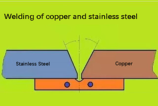
Welding copper to stainless steel is a critical yet challenging process in modern metallurgy, primarily due to the inherent risk of copper penetration cracking. This phenomenon, also known as liquid metal embrittlement (LME), occurs when molten copper infiltrates the grain boundaries of stainless steel, compromising the joint’s structural integrity.
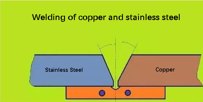
To mitigate the risk of penetration cracking, a two-pronged approach is essential:
By meticulously adhering to these guidelines, fabricators can significantly reduce the risk of penetration cracking and achieve robust, high-integrity joints between copper and stainless steel. This approach not only ensures structural soundness but also optimizes the welded component’s performance in demanding applications across industries such as petrochemical, power generation, and advanced manufacturing.
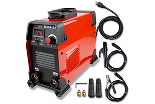
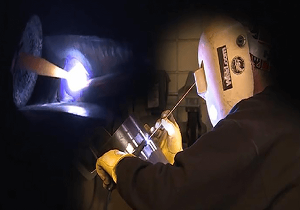
When using manual arc welding for copper and stainless steel, it’s important to keep in mind that selecting an austenitic stainless steel electrode can increase the likelihood of thermal cracking.
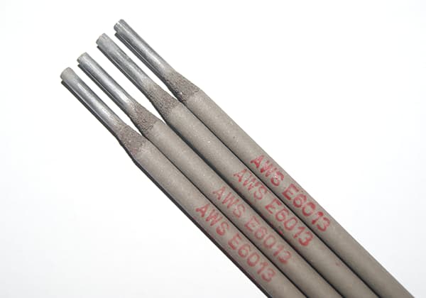
For this reason, it’s advisable to choose a nickel copper welding rod (70% nickel and 30% copper), or a nickel-based alloy electrode. An alternative is to use a copper welding rod (T237).
Related reading: How to Choose the Right Welding Rod?
During the welding process, it’s recommended to adopt a fast welding technique using a small diameter and low current, without swinging the arc. The arc should also be inclined towards the copper side to reduce the risk of penetration cracks.
In submerged arc welding (SAW) of copper to stainless steel, the primary challenges are preventing crack formation and minimizing porosity. These issues are particularly critical due to the dissimilar thermal and mechanical properties of the materials.
To mitigate these concerns, meticulous surface preparation is essential. Thoroughly clean and degrease the surfaces of both the weldments and welding wires immediately prior to welding. This step removes contaminants that could lead to inclusions or compromise weld integrity.
For weldments with thicknesses ranging from 8 to 10mm, a 70° asymmetric V-shaped groove is typically employed. The groove angle on the copper side is set at 40°, while the stainless steel (1Cr18Ni9Ti) side is beveled at 30°. This asymmetry accommodates the different thermal conductivities of the materials.
A flux of either HJ431 or HJ430 is recommended. The HJ430 flux should be baked at 200°C for 2 hours to remove moisture, which is crucial for reducing hydrogen-induced porosity. Use a copper-based welding wire as the primary filler material. To promote better metallurgical bonding and reduce the risk of cracking, place one to three nickel or nickel-copper alloy wires strategically within the groove. These act as a transitional layer between the dissimilar metals.
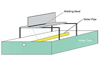
To ensure adequate penetration and fusion, employ higher welding energy levels than those typically used for similar metal welding. Utilize a water-cooled copper backing bar to control the heat input and prevent excessive melting of the copper base material. Position the welding wire to favor the copper side, approximately 5 to 6mm offset from the groove centerline. This technique compensates for the higher thermal conductivity of copper and promotes more even heat distribution across the joint.
Monitor and control the interpass temperature carefully to manage thermal stresses and prevent hot cracking. Post-weld heat treatment may be necessary to relieve residual stresses and optimize the mechanical properties of the welded joint.
Process parameters of submerged arc welding of pure copper and stainless steel
| Weldment | Joint form | Thickness mm | Welding wire diameter mm | Welding current A | Welding voltage V | welding speed mm/s | Wire feeding speed cm/min |
|---|---|---|---|---|---|---|---|
| T2+1Cr18Ni9 | Butt V | 10-10 | 4 | 600-650 | 36-38 | 6.4 | 232 |
| 12-12 | 4 | 650-680 | 38-42 | 6.0 | 227 | ||
| 14-14 | 4 | 680-720 | 40-42 | 5.6 | 223 | ||
| 16-16 | 4 | 720-780 | 42-44 | 5.0 | 217 | ||
| 18-18 | 5 | 780-820 | 44-45 | 4.5 | 213 | ||
| 20-20 | 5 | 820~850 | 45-46 | 4.3 | 210 |
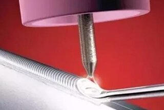
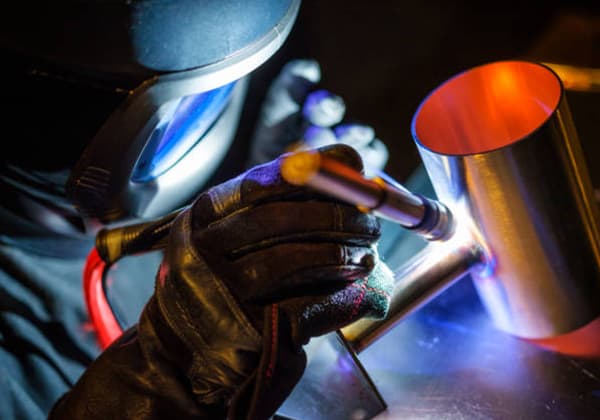
TIG welding can produce high-quality joints when joining copper, copper alloys, and stainless steel. However, achieving optimal results requires mastery of specific techniques. The primary joint configurations are butt and corner joints in a groove. For dissimilar metal welding, it’s recommended to prepare a half V-groove on the stainless steel side while leaving the copper side square.
Prior to welding, thorough surface preparation is crucial. Clean the weldment surfaces and apply a specialized flux composition (70% H3BO3, 21% Na2B4O2, 9% CaF2) to both the front and back sides of the joint. Allow the flux to dry completely before initiating the welding process.
Filler metal selection is critical for successful dissimilar metal welding. Preferred options include Monel alloy (70% Ni, 30% Cu) or copper alloys containing silicon and aluminum, such as HS221, QAI9-2, QAI9-4, QSi3-1, or QSn4-3. These filler metals enhance weldability and mechanical properties of the joint.
During TIG welding, precise arc positioning is essential. Bias the tungsten arc towards the copper side, maintaining a 5-8mm offset from the groove centerline. This technique helps control the melting of the stainless steel, reducing the risk of intermetallic compound formation.
The welding process typically employs copper, copper-nickel, or aluminum-bronze filler wires. These materials improve the mechanical properties of the weld metal and mitigate the risk of copper penetration cracking. A straight bead technique without oscillation is generally preferred, utilizing higher travel speeds to minimize heat input.
When implementing an argon arc welding-brazing hybrid process, minimize melting on the stainless steel side. This approach creates a brazed connection on the stainless steel interface and a fusion welded joint on the copper side, optimizing the metallurgical compatibility between the dissimilar metals.
Refer to the accompanying figure for specific process parameters when TIG welding brass to stainless steel. These parameters serve as a starting point and may require fine-tuning based on material thickness, joint design, and specific alloy compositions.
TIG welding of brass H62Sn-1 and stainless steel 1Cr18Ni9Ti
| Weldment thickness mm | Tungsten electrode diameter mm | Tungsten electrode extension length | Nozzle diameter mm | Welding current a | Argon flow L / min |
| 3+3 | 3 | 5-6 | 12 | 100~120 | 10 |
| 3+6 | 3 | 5-6 | 12 | 140-180 | 10 |
| 3+18 | 3 | 5-6 | 12 | 150-200 | 10 |
Gas welding, when applied to copper and stainless steel, presents unique challenges due to the lower flame temperature compared to arc welding processes. This temperature differential can lead to several complications:
To address these challenges, proper filler metal selection is crucial. For joining pure copper to 18-8 stainless steel, copper-zinc alloy welding wires such as HSCuZn-2 (60% Cu, 40% Zn), HSCuZn3 (59% Cu, 41% Zn), or HSCuZnNi (54-56% Cu, 43.5-45.5% Zn, 0.5-1.5% Ni) are commonly employed. These filler metals offer a balance of strength, corrosion resistance, and compatibility with both base metals.
For neutral flame welding, 301 welding powder (typically a mixture of borax, boric acid, and other fluxing agents) or pure borax can be used as a flux to protect the weld pool from oxidation and improve wetting characteristics.
When dealing with longer welds, a technique to mitigate the heat input discrepancy involves depositing a layer of brass on the groove surface of the stainless steel side prior to welding. This intermediate layer serves as a thermal buffer and helps to equalize the heat distribution between the two dissimilar metals during the welding process.
To optimize gas welding of copper to stainless steel, consider the following best practices:
When brazing copper to stainless steel, silver-based solders are predominantly used due to their excellent wetting properties and lower melting points. Common alloys include HL302 (56% Ag), HL309 (50% Ag), and HL312 (45% Ag), each offering specific advantages depending on the application requirements. The brazing process follows general principles but requires careful attention to temperature control and heat distribution.
Key considerations for copper-stainless steel brazing include:

