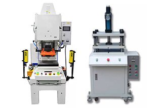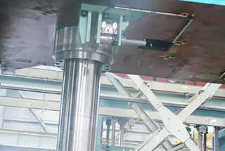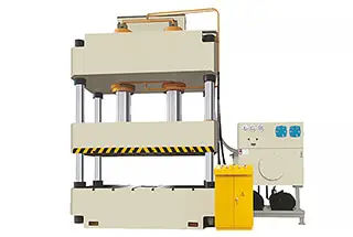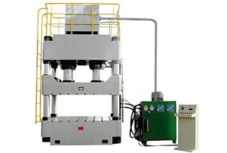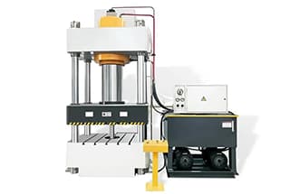
Have you ever wondered about the incredible power of hydraulic presses? These marvels of engineering can exert immense force, transforming materials in ways that seem almost magical. In this blog post, we’ll dive into the fascinating world of hydraulic press machines, exploring their history, types, and working principles. Get ready to be amazed by the sheer might of these mechanical wonders!
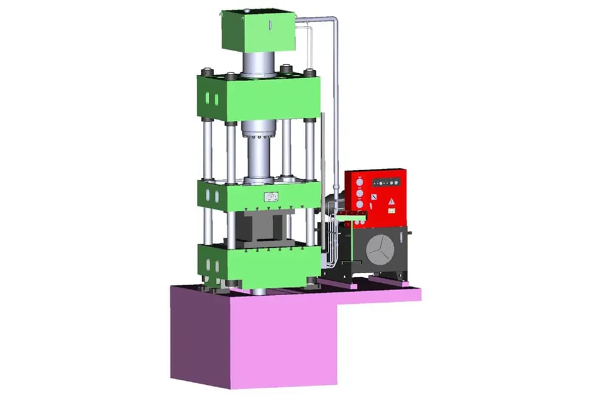
A hydraulic press is a sophisticated machine that harnesses the power of fluid dynamics to generate immense force, leveraging Pascal’s principle to perform a wide array of industrial tasks. This versatile equipment transforms fluid pressure into mechanical force, enabling precise and controlled compression, forming, and shaping of materials.
Typically, a hydraulic press machine comprises three essential components:
These integrated systems work in concert to deliver controlled force, making hydraulic presses indispensable in various industries, from automotive manufacturing and aerospace to metalworking and materials testing.

Further reading:
The hydraulic press machine (also known as a hydraulic oil press) harnesses the principle of hydrostatic pressure to process a wide range of materials, including metals, plastics, rubber, wood, and powder-based products. This versatile equipment operates by transmitting force through an incompressible fluid, typically hydraulic oil, to generate immense pressure for material deformation and shaping.
Widely employed in manufacturing industries, hydraulic presses are indispensable for various pressing and forming operations. These applications encompass:
The hydraulic press’s ability to deliver precise, controlled force makes it an essential tool in modern manufacturing, enabling the production of complex parts with high accuracy and repeatability across diverse industries.
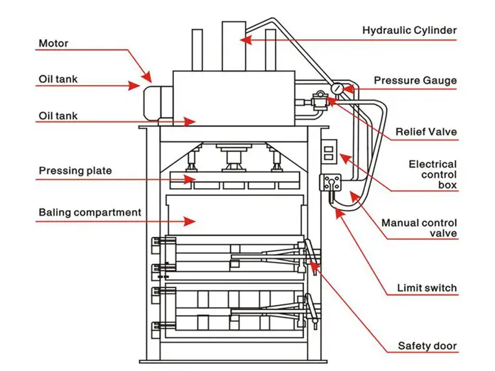
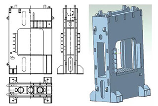
Fig.2 Hydraulic Press Machine Structure
Biggest Hydraulic Press
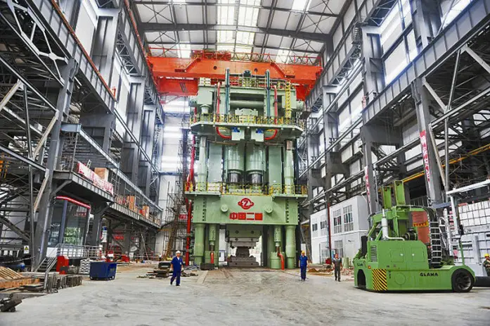
Fig.3 80,000 Ton Die Forging Press
The 80,000-ton die-forging hydraulic press stands 27 meters tall on the ground and 15 meters underground, making it a total height of 42 meters and a total weight of 22,000 tons, thereby earning its title as the world’s most powerful and strongest hydraulic press.
As a national treasure-class strategic equipment, the giant die-forging hydraulic press represents the strength of the heavy industry. Only a few countries in the world possess the capability to manufacture such a hydraulic forging press.
Presently, only China, the United States, Russia, and France possess die-forging presses with a capacity of over 40,000 tons.
The United States constructed two of the largest 45,000-ton die-forging presses in the world in 1955, and they are still in operation today. In 2001, another 40,000-ton die-forging press was erected at the Shultz Steel Mill in California.
The Soviet Union built two massive 75,000-ton die-forging presses in 1961. France acquired a 65,000-ton die-forging press from the Soviet Union in 1976 and developed a 40,000-ton die-forging press in collaboration with Germany in 2005.
China’s first 30,000-ton die-forging press remained inactive for almost 40 years after it was built in 1973. However, in the last two years, several massive presses have been developed rapidly, with 30,000-ton, 40,000-ton, and 80,000-ton die-forging presses being built in 2012 alone.
The 80,000-ton hydraulic press broke the world record previously held by the Soviet Union for 51 years.
The die-forging press is primarily used to produce high-strength titanium/aluminum alloy forgings for industries such as aerospace, nuclear power, and petrochemicals.
Any country possessing a large die-forging press is considered to have a formidable aviation industry globally.
In 1795, British engineer Joseph Bramah applied Pascal’s principle to invent the hydraulic press, initially used for pressing and packaging vegetable oils. This innovation marked the beginning of hydraulic technology in manufacturing processes.
By the mid-19th century, Britain pioneered the use of hydraulic presses for metal forging, gradually superseding the massive steam hammers. This transition signified a major leap in forging technology, offering more precise control and greater force application.
Towards the end of the 19th century, the United States demonstrated its industrial prowess by constructing 126,000-ton free-forging hydraulic presses. This achievement highlighted the rapid advancement in hydraulic press technology and its increasing capacity.
Since then, global manufacturing has produced over 20 sets of 10,000-ton free-forging hydraulic machines, including two manufactured in China (as illustrated in Figure 4). These large-scale presses enabled the production of massive, high-integrity components for industries such as aerospace, shipbuilding, and heavy machinery.
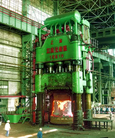
The evolution of electric high-pressure pump technology has driven the development of forging hydraulic presses towards more compact and efficient designs. This trend has allowed for greater versatility and reduced energy consumption in metal forming processes.
In the 1950s, the introduction of small and fast forging hydraulic presses revolutionized the industry. These machines could perform tasks equivalent to those of a 3-5 ton forging hammer, but with improved precision and energy efficiency. This innovation expanded the application of hydraulic presses in various manufacturing sectors.
Germany’s production of an 18,000-ton die-forging press in the 1940s marked another milestone in hydraulic press technology. Subsequently, 18 sets of 18,000-ton forging hydraulic machines have been created worldwide. China has further advanced this technology, manufacturing a 30,000-ton press, showcasing its growing capabilities in heavy industrial equipment production.
These developments in hydraulic press technology have significantly impacted metal forming processes, enabling the production of larger, more complex components with improved accuracy and efficiency. The ongoing evolution of hydraulic presses continues to shape modern manufacturing capabilities across various industries.
According to the structural form, the hydraulic press machine is mainly divided into:
If classified by tonnage, the hydraulic press can be divided into:
According to the applications, it is mainly divided into metal forming, bending, stretching, punching, powder (metal, non-metal) forming, pressing, extrusion and so on.
Hot forging hydraulic press
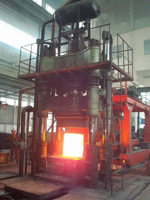
As one of the most frequently used equipment in the forging industry, the large hydraulic forging machine is capable of performing various free forging techniques.
Currently, there are several series of forging hydraulic presses with specifications of 800, 1600, 2000, 2500, 3150, 4000, and 5000 tons.
Four-column hydraulic press
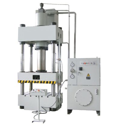
The four-post hydraulic press is ideal for pressing plastic materials, such as powder product forming, plastic product forming, cold (hot) extrusion metal forming, sheet drawing, transverse pressing, bending, stamping, and correction processes.
The four-post hydraulic press can be further divided into four-post two-beam hydraulic press, four-post three-beam hydraulic press, and four-post four-beam hydraulic press.
C-frame hydraulic press
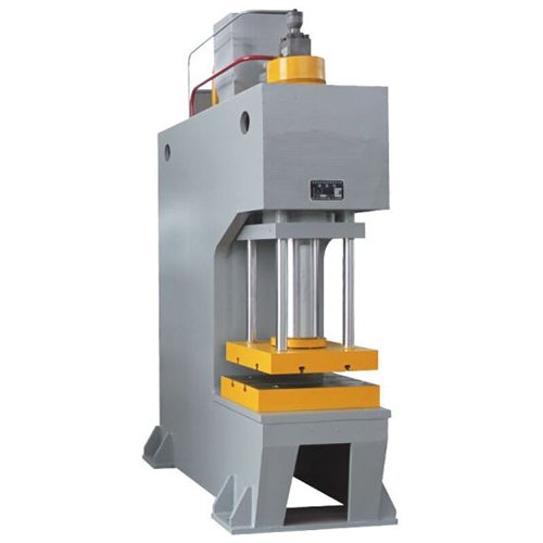
The working range of the hydraulic press can be extended by using a three-sided space with maximum retractability of 260mm-800mm.
It also has the ability to preset the working pressure and is equipped with a heat abstraction device.
Horizontal hydraulic press
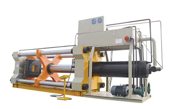
The machine parts can be assembled, disassembled, straightened, compressed, stretched, bent, punched, and more, making it a versatile machine.
The working table of the machine is designed to move up and down, expanding the opening and closing height of the machine for added convenience in use.
Two-pillar hydraulic press
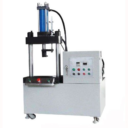
This series of products is suitable for pressing, bending, and shaping all types of parts, including stamping indentations, flanging, punching, and light stretching of small parts. It is also suitable for forming metal powder products.
With electric control, it has job motion and semi-automatic cycle capabilities, which can protect against pressure delay time.
It also has a good sliding block direction, is easy to operate and maintain, and has economic durability.
Users can add thermal instruments, an ejector cylinder, a travel display, and counting functions as needed. The two-pillar hydraulic press is based on Pascal’s law and utilizes fluid pressure transmission.
There are many types of two-pillar hydraulic presses, which can be divided into oil presses and water presses based on the type of liquid that transfers pressure.
Water presses produce a large total pressure and are often used for forging and stamping.
Forging presses are further divided into die forging water presses and free forging water presses. Die forging water presses require the use of a mold, while free forging water presses do not.
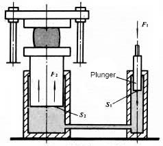
Fig.5 Hydraulic press mechanism
The area of the large and small plungers are S2 and S1, respectively, and the forces on them are F2 and F1, respectively.
According to Pascal’s principle, the pressure of the confined liquid is equal everywhere, meaning F2/S2 = F1/S1 = p; F2 = F1(S2/S1).
The gain effect of hydraulic pressure is the same as mechanical gain, meaning the force is increased but the work is not gained. As a result, the motion distance of the large plunger is S1/S2 times that of the small plunger.
The basic principle of the hydraulic press is that an oil pump transfers hydraulic oil to integrated cartridge valve blocks, which are then directed to the upper or lower chamber of the cylinder through a one-way valve and a relief valve.
Under the action of high-pressure oil, the oil cylinder begins to move up and down.
The hydraulic press is a device that makes use of liquid to transfer pressure, utilizing Pascal’s law in the transfer of pressure within a closed container.
The four-column hydraulic press’s hydraulic drive system consists of power mechanism, control mechanism, executive mechanism, auxiliary mechanism, and working medium.
Typically, an oil pump is used as the power mechanism, with one or more pumps selected to meet the requirement of the actuator’s running speed.
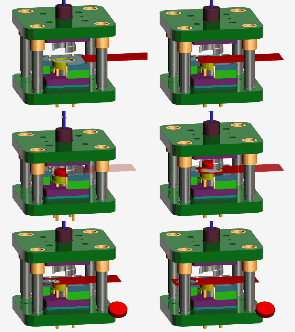
Working Medium
The function of the working medium used in a hydraulic press is not only to transfer pressure, but also to ensure that the components of the hydraulic press machine are sensitive, reliable, long-lasting, and have minimal leakage.
The basic requirements for a working medium in a hydraulic press are:
Historically, water was used as the working medium in hydraulic presses.
Later, emulsified liquid was introduced by adding a small amount of oil to the water to improve lubrication and reduce corrosion.
Mineral oil was later introduced as the working medium in hydraulic presses in the late 19th century. The oil had good lubricity, anti-corrosive properties, and moderate viscosity, which improved the performance of hydraulic presses.
In the second half of the 20th century, a new type of water-based emulsifying solution was developed, characterized as “oil-in-water” rather than “water-in-oil.”
This solution had properties similar to oil, including good lubrication and anti-corrosion properties, but with the added benefit of containing little oil and being less flammable.
However, the higher cost of water-based emulsions has limited their widespread use.
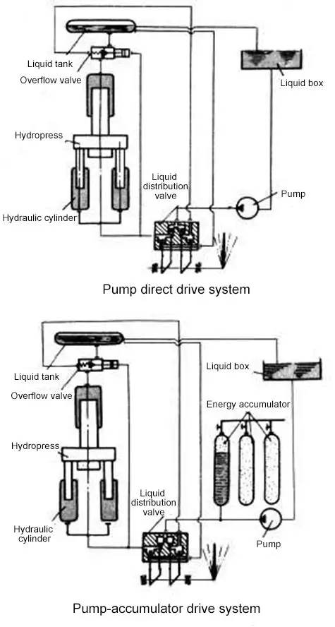
Fig.6 Hydraulic press machine drive system
The driving system of hydraulic press mainly consists of two types: pump direct drive and pump-accumulator drive.
Pump Direct Drive:
In this system, the pump provides high-pressure working fluid to the hydraulic cylinder, and a distribution valve is used to change the direction of the supply liquid.
The overflow valve is used to adjust the limited pressure of the system and acts as a safety overflow.
This drive system is simple in structure, has fewer processes, and the pressure can automatically increase and decrease according to the work required force, which reduces power consumption.
However, the capacity of the pump and drive motor must be determined based on the largest required force and maximum working speed of the hydraulic press.
This type of drive system is mainly used for medium and small-sized hydraulic presses and can also be used for large (such as 12000T) free forging hydraulic presses that are directly driven by the pump.
Pump-Accumulator Drive:
This system has one or a set of accumulators, and when the high-pressure working fluid supplied by the pump is in surplus, it is stored by the accumulator.
When the supply is insufficient to meet the demand, it is supplied by the accumulator.
The capacity of the pump and motor can be selected based on the average amount of high-pressure working fluid required if this system is adopted.
However, the energy consumption is high, the system has many processes, and the structure is complex due to the constant working fluid pressure.
This type of drive system is used for large hydraulic presses or a set of the drive system to drive several hydraulic presses.
According to the direction of force, hydraulic presses are classified into vertical and horizontal types. The majority of hydraulic presses are vertical, while those used for extrusion are horizontal.
In terms of structure type, hydraulic presses can be two-column, four-column, eight-column, welding frame, and multi-layer steel strip winding frame types. Medium and small vertical hydraulic presses usually have a C-frame type.
The C-frame hydraulic press is open on three sides and is easy to operate, but it has a lower degree of rigidity.
The welding frame hydraulic press, used for stamping, is rigid and open at the front and back, but closed on the left and right.
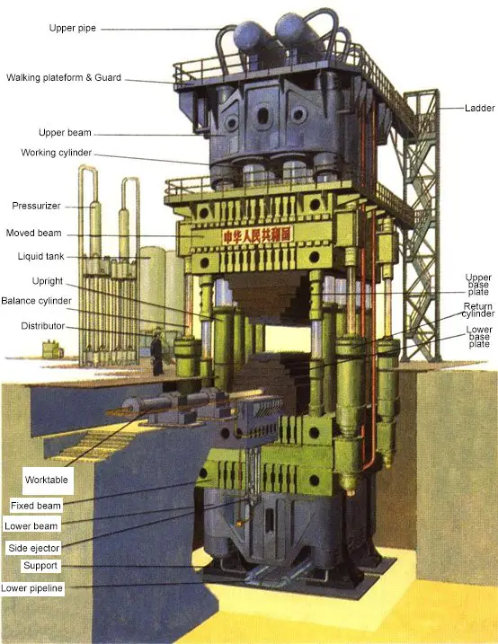
In a vertical transmission four-column free forging hydraulic press, the oil cylinder is fixed on the upper beam, and the plunger is firmly attached to the movable beam.
The movable beam moves up and down under the pressure of the working fluid, guided by the vertical column.
The movable beam has workbenches that move back and forth, with an upper anvil and lower anvil installed respectively under the movable beam and on the worktable.
The working force is supported by a frame composed of upper and lower beams and columns.
Large and medium-sized free forging hydraulic presses, which are typically driven by a pump-accumulator system, usually adopt three working cylinders to achieve three-level working forces.
There are also balancing cylinders and return cylinders outside the working cylinders that apply upward force.
Compared to traditional stamping methods, hydroforming boasts clear technical and economic benefits such as weight reduction, decreased number of parts and molds, improved rigidity and strength, and reduced production costs.
This technology is seeing increasing use in various industries, particularly in the automotive sector.
The goal of reducing structural weight and energy consumption during operation is a long-term objective in industries such as automobiles, aviation, and aerospace.
Hydroforming is an advanced manufacturing technology that helps achieve this goal and is a trend in the development of advanced manufacturing.
In comparison to stamping and welding technologies, hydroforming has several key advantages:
Decreased weight and material savings:
For parts such as engine brackets and radiator brackets, hydroformed parts can be 20-40% lighter than stamped parts. For hollow step shaft parts, weight reduction can reach 40-50%.
Reduced number of parts and molds and lower mold costs:
Hydroformed parts typically only require one set of molds, whereas many stamped parts require multiple sets.
Hydroforming has reduced the number of engine bracket parts from 6 to 1 and radiator bracket parts from 17 to 10.
Lower subsequent machining and assembly welding:
For example, the radiator support has seen a 43% increase in heat dissipation area, a decrease in soldering points from 174 to 20, a decrease in processes from 13 to 6, and a 66% increase in productivity.
Improved strength and rigidity, especially fatigue strength:
For instance, the rigidity of a hydroformed radiator bracket can increase by 39% in the vertical direction and 50% in the horizontal direction.
Lower production costs:
Statistical analysis of hydroformed parts has shown that the average production cost is 15-20% lower than that of stamped parts, and mold costs are 20-30% lower.”
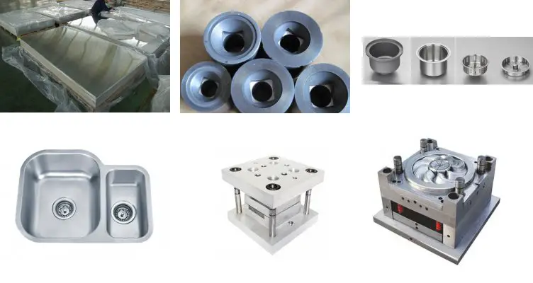
Hydraulic presses can be utilized for various metal sheet forming processes such as drawing, turning, bending, and stamping. It can also be adapted for general pressing needs with the addition of blanking buffer, blanking, and moving table devices, as per the user’s requirements.
In addition to forging and forming, the three-beam four-column hydraulic press can also be utilized for correction, press fitting, packaging, briquetting, and plate pressing.
Materials suitable for the hydraulic forming process include carbon steel, stainless steel, aluminum alloy, copper alloy, and nickel alloy.
In general, any material suitable for cold forming can be used in the hydraulic forming process.
Hydraulic forming technology is widely used in various industries, including automobile factories, electronics factories, electric appliance factories, heat treatment plants, gear factories, and air conditioning parts factories.
Additionally, hydraulic forming is widely used in the automobile, aviation, aerospace, and pipeline industries. It is mainly applicable to:
| 1 | The gear pump |
| 2 | Hydraulic overflow valve |
| 3 | Miniature contactor |
| 4 | Proximity switch |
| 5 | O-ring |
| 6 | U-ring |
| 7 | Anti-dust ring |
| 8 | Guide ring |
| 9 | Ladder ring |
| 10 | Hole use YX ring |
| 11 | Combined seal ring |
| 12 | The gear pump |
DIY 5 ton hydraulic press
Different types of hydraulic press machines operate differently, and every hydraulic press manufacturer will provide an operation manual along with the machine upon delivery.
This manual serves as the best training material for learning the key points of how to use the hydraulic press.
As a user of a four-pillar hydraulic press machine, you can also refer to our hydraulic press user manual for further information.
Note: Each hydraulic press machine operates differently, and the manufacturer will provide an operation manual with the machine. This manual will be the best training material for learning how to use the machine.
At this point, the whole commissioning of hydraulic press machine is finished and can be put into production.
The recommended lubricant for hydraulic press machines is ISO VG 32 or ISO VG 46 anti-wear hydraulic oil, with an optimal operating temperature range of 15°C to 60°C (59°F to 140°F). These oils provide excellent wear protection and thermal stability for high-pressure systems.
Prior to filling the reservoir, the hydraulic fluid must undergo rigorous filtration to eliminate contaminants that could compromise system performance and component longevity. Implement a filtration system with a minimum Beta ratio of β10 ≥ 200.
Replace the hydraulic oil annually, with the initial change occurring no later than three months after commissioning. Regular oil analysis should be conducted to monitor contamination levels and oil degradation.
Maintain proper lubrication of the sliding blocks using high-quality lithium-based grease. Keep the vertical columns clean and free from debris. Apply machine oil to all moving parts before each operating cycle to minimize wear and ensure smooth operation.
For a press with a nominal capacity of 500 tonnes, the maximum allowable eccentricity of the central load is 40mm. Exceeding this limit can induce post-tension effects, potentially leading to misalignment, uneven wear, or structural damage. Implement load-sensing systems to prevent overloading.
Calibrate and inspect pressure gauges biannually using certified equipment. Consider implementing digital pressure transducers for enhanced accuracy and real-time monitoring capabilities.
During extended periods of inactivity, thoroughly clean all exposed surfaces and apply a high-quality, long-lasting rust preventative coating. Store the machine in a climate-controlled environment when possible to minimize corrosion risks.
Implement a comprehensive preventive maintenance schedule, including regular inspections of seals, hoses, and electrical components. Keep detailed maintenance logs and use predictive maintenance techniques, such as vibration analysis and thermography, to identify potential issues before they lead to failures.
The primary maintenance for the hydraulic press machine is to be conducted after it has run for 500 hours, with the responsibility primarily falling on the operators and with support from maintenance workers.
To begin maintenance, make sure first to turn off the power supply, then proceed according to the maintenance schedule outlined in the table below.
| No. | Position | Maintenance details and requirements |
| 1 | External maintenance | 1. Clean the outside surface of hydraulic press, maintain inside and outside clean, no rust. |
| 2. Complete the missing screws, nuts, buttons, signs, etc. | ||
| 2 | Beam, column guide | 1. Clean the outer surface of upper and lower beams and movable beams, as well as pillar, guide rail, slide block and press plate. Clean without oil, yellow robe and rust stain. |
| 2. Remove the burrs on the bottom surface of the movable beam and the upper surface of the lower beam as well as on the pillar, guide rail and slider. | ||
| 3. Check and tighten the fasteners of the beam and column guide rails. | ||
| 3 | Hydraulic, lubrication | 1. Wipe and check the surface of oil pump, valve, oil tank and pipeline, clean, rust free, oil free, no yellow robe, no leakage. |
| 2. Clean the oil cup, filter screen, dredge the oil road, the oil mark is clear. | ||
| 3. Check the oil quality and quantity in the fuel tank, add lubricating oil as appropriate. | ||
| 4. Check gauge | ||
| 5. Check the lubrication of columns and guide rails. | ||
| 4 | Electric | 1. Clean the electrical box without dirt or grease. |
| 2. Check the integrity of the line, hose protection connection reliable, good performance. | ||
| 3. Check the travel switch of movable beam, check whether the action is sensitive and reliable. | ||
| 4. Safety protective cover, pillar protective cover complete and easy to use, foot pedal switch protective cover intact, safe and reliable. | ||
| 5. Check and tighten the zero connecting device. |
| No. | Position | Maintenance details and requirements |
| 1 | Beam, column guide | 1. Check and adjust the horizontal plane of the beam, guide rail, guide sleeve, slide block and press plate of the column so as to achieve smooth movement and meet the technical requirements. |
| 2. Repair or replace defective parts. | ||
| 2 | Hydraulic, lubrication | 1. Disassemble and repair solenoid valve, grinding valve and valve core. |
| 2. Clean and inspect oil pump, cylinder and plunger, repair burrs and replace oil seal. | ||
| 3. Check pressure gauges. | ||
| 4. Repair or replace badly worn parts. | ||
| 5. Start the hydraulic press machine to check whether the movement of each cylinder and plunger is smooth, no crawling. Check whether the support valve can stop the moving beam in any position accurately and the pressure drop meets the process requirements. | ||
| 3 | Electric | 1. Clean motor, check bearing and replace grease. |
| 2. Repair or replace damaged components. | ||
| 3. The electrical appliances meet the requirements of the equipment standard. | ||
| 4 | Accuracy | 1. Calibrate machine tool level, check, adjust and repair accuracy. |
| 2. Accuracy in accordance with the equipment integrity standards. |
You can check out the common faults and troubleshooting solutions for hydraulic press machine in our previous written article.
Safety regulations
Only authorized personnel with thorough knowledge of the hydraulic press machine’s structure, performance, and operating procedures should operate the equipment.
Never attempt to overhaul, adjust, or tamper with the machine while it is in operation. Always ensure the press is fully stopped and de-energized before maintenance.
If serious oil leakage, unreliable operation, loud noise, excessive vibration, or any other abnormal conditions occur, the operator must immediately shut down the machine and investigate the root cause before resolving the issue.
Do not operate the machine under overload conditions or when the maximum eccentricity is exceeded. Adhere to the press’s rated capacity and load distribution specifications at all times.
Strictly observe the maximum stroke limit of the slider. The minimum closing height of the mold must not be less than 600mm to prevent damage to the press and ensure operator safety.
Ensure all electrical equipment is securely and reliably grounded to prevent electrical hazards and potential malfunctions.
At the conclusion of each work shift, return the slider to its lowest position to relieve hydraulic pressure and minimize the risk of unexpected movement.
Regularly inspect and maintain safety devices, including guards, light curtains, and emergency stop buttons. Never bypass or disable these critical safety features.
Wear appropriate personal protective equipment (PPE) such as safety glasses, hearing protection, and steel-toed shoes when operating or working near the hydraulic press.
Implement a lockout/tagout procedure for maintenance and repair activities to prevent accidental start-up or energization of the machine.
The hydraulic press is becoming increasingly popular in industrial production due to advancements in industry and hydraulic technology.
Regardless of whether you are a manufacturer or user of a hydraulic press, it is crucial to understand how to calculate hydraulic press tonnage.
As a professional manufacturer, we will provide you with information on the amount of force exerted by a hydraulic press and the significance of this information.
In order to determine the tonnage of the hydraulic cylinder, it is necessary to know the working pressure of the hydraulic system and the inner diameter and outer diameter of the cylinder rod (which will be required when calculating the tensile force of the hydraulic cylinder).
The equation for hydraulic press tonnage calculation formula:
Pushing force of hydraulic cylinder = Hydraulic cylinder inner section area (or the piston sectional area) × working pressure
Hydraulic cylinder inner section area = π*D2/4 = 3.14 × D2 ÷ 4
Working pressure: equals to the pressure shown on the pressure gauge during the maximum load operation
For example:
Assuming the hydraulic cylinder has an inner diameter of 10cm and a working pressure of 16MPa (160kgf).
The inner section area of the hydraulic cylinder can be calculated as follows: 3.14×10×10÷4=78.5cm2
Therefore, the pushing force can be calculated as follows: 78.5 x 160 = 12560kg = 12.56 tons.
To make it easier, we have created a hydraulic press tonnage calculator.
By using this formula, we can quickly determine the tonnage of the hydraulic press that we have purchased or are looking to purchase, and avoid paying a high price for equipment with a low tonnage.
Additionally, we can calculate the working pressure of our own hydraulic press with this formula in order to prevent overloading the equipment and improve its longevity and performance.
Before purchasing a hydraulic press machine, you may be wondering what size is best suited for your needs. This issue can easily be resolved by using the hydraulic press tonnage calculation formula outlined above.
However, you may find yourself unsure of where to buy the hydraulic press. There are many factors that could influence your decision, and there are many reputable hydraulic press machine manufacturers around the world.
Despite this, the most cost-effective hydraulic press machines are often produced by manufacturers in China.
It is important to take the time to find a reliable and trustworthy hydraulic press manufacturer, which will provide you with all the necessary specifications and cost information for the hydraulic press you require.
Further reading:
The fascination with hydraulic press crushing experiments stems from a desire to understand material properties and structural integrity under extreme compressive forces. The crushing potential of a hydraulic press depends primarily on its tonnage capacity, which directly correlates to the maximum force it can exert.
Hydraulic presses typically range from small benchtop units capable of exerting a few tons of force to massive industrial machines that can generate thousands of tons. The material properties of the object being crushed—such as yield strength, compressive strength, and structural design—determine its resistance to deformation and failure under pressure.
For those with access to a hydraulic press in their workshop, conducting controlled crushing experiments can provide valuable insights into material behavior and structural design principles. However, it’s crucial to adhere to strict safety protocols, including proper machine operation, protective equipment usage, and safe handling of crushed materials.
Some common materials and their general resistance to hydraulic press crushing:
Future experiments could explore advanced materials, complex geometries, or even simulate real-world scenarios to enhance our understanding of material performance under extreme compressive loads. Such research has practical applications in fields like materials science, structural engineering, and manufacturing process optimization.
The following list encompasses seven critical terms in hydraulic press operations. While seasoned engineers and operators should be well-versed in these concepts, they may be unfamiliar to newcomers. Let’s examine each in detail:
Nominal Pressure: The maximum continuous operating pressure a hydraulic system is designed to withstand without compromising performance or safety. It’s typically expressed in bar or PSI and is a crucial factor in determining the press’s capabilities and limitations.
Motive Seal: A dynamic sealing mechanism crucial for maintaining fluid integrity in the sliding components of a hydraulic press. These seals, often made of materials like polyurethane or PTFE, prevent leakage and ensure efficient power transmission while accommodating reciprocating or rotating motion.
Circuit Diagram: A schematic representation of the hydraulic system using standardized symbols (ISO 1219-1:2012) to depict components such as pumps, valves, cylinders, and their interconnections. This diagram is essential for system design, troubleshooting, and maintenance.
Hydraulic Drive System: The core power conversion unit in a hydraulic press, transforming fluid pressure into mechanical force and motion. It typically consists of a hydraulic pump, control valves, actuators (cylinders or motors), and auxiliary components working in tandem to deliver precise force and movement.
Hydraulic Power Unit (HPU): Often referred to as a hydraulic pressure station, this is the central power source for the hydraulic system. It comprises a reservoir, hydraulic pump(s), electric motor(s), control valves, filters, heat exchangers, and instrumentation. The HPU generates, conditions, and distributes hydraulic fluid to drive the press operations.
Hydraulic Balance: A critical concept in press design that involves using fluid pressure to counteract the weight of moving components and the press itself. This balance enhances efficiency, reduces wear, and enables smoother operation, particularly in large-scale presses.
Oil Drainage: The process of returning hydraulic fluid from various system components back to the reservoir. Proper drainage design is crucial for system efficiency, preventing cavitation, and maintaining fluid cleanliness. It often involves strategically placed return lines, filters, and potentially cooling mechanisms.
Hydraulic press drawing refers to the process of positioning the blanking part in the mold during the hydraulic press drawing. The blanking ring controls the flow of metal to form a hollow workpiece.
In general, deep drawing refers to a workpiece whose depth is greater than 1/2 of its diameter.
The blanking process in a punching machine involves cutting and punching the plate to form the desired shape. The material used can be a single sheet or a continuous strip.
Stamping encompasses not only blanking but also forming, bending, flanging, and hole punching processes.
If the drawing process is added to the blanking process on a punch machine, the press can be referred to as a hydraulic punch press.
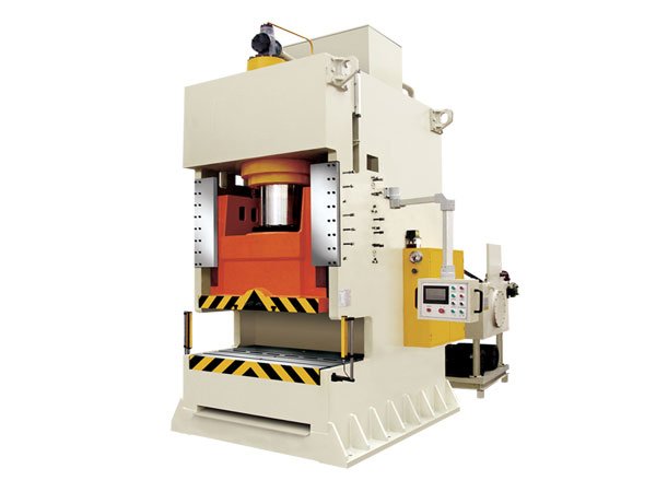
In general, punching machines have a simple structure, fast production speed, and high efficiency, making them suitable for high-volume and simple blanking forming.
On the other hand, hydraulic presses are better suited for the production of medium to small batches with a need for accuracy, depth, and a changeable shape.
These presses have precise requirements for the slider velocity, pressure, and position, and can be custom-made to meet specific orders.
When customers are looking to purchase processing machinery, they should choose the appropriate hydraulic or mechanical press based on their actual processing needs.
5 Ton Hydraulic Jack vs 500 Ton Hydraulic Press
After reading the above information, you should now have a comprehensive understanding of hydraulic presses.
If you are in the market to buy a hydraulic press for your workshop, this article on purchasing one may be of help to you.
Additionally, you can reach out to us to get a quote for a hydraulic press.

