Metal tubes are extensively used in a variety of industries, including aerospace manufacturing, construction machinery, the automotive industry, petrochemicals, and agricultural equipment. Different applications require parts of various shapes and sizes to meet the diverse needs of these industries.
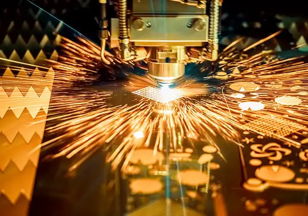
Laser processing technology is particularly well-suited for working with various types of metal tubes. Tube laser cutting systems are characterized by their high flexibility and automation, enabling the production of small batches of different materials and product types.
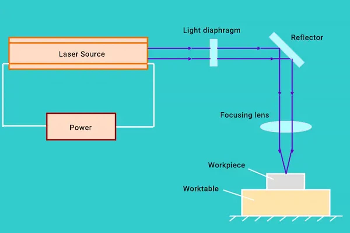
Beam Guidance and Focusing System
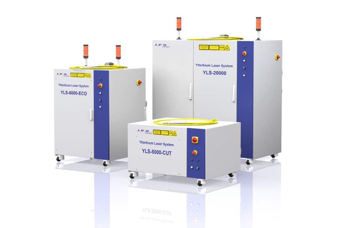
The beam guidance and focusing system directs the laser beam emitted from the generator to the cutting head’s focusing optics. For laser tube cutting, achieving a high-quality kerf requires a focused laser beam with a small diameter and high power, which necessitates low-order mode output from the laser generator.
To obtain a smaller focused beam diameter during tube cutting, the laser should operate in a lower-order transverse mode, ideally in the fundamental mode. The cutting head of the laser cutting equipment is equipped with a focusing lens, which allows the laser beam to be focused into a small spot, enabling high-quality tube cutting.
Cutting Head Trajectory Control
In tube cutting, the workpiece is typically a complex spatial curved surface. Traditional programming methods can be challenging, thus requiring operators to select the correct processing path and appropriate reference points based on the requirements of the process.
The numerical control system records the feed of each axis and the coordinates of the reference points. The spatial linear and circular interpolation functions of the laser cutting system are utilized to record the coordinates during the process and generate the machining program.
Automatic Control of the Laser Cutting Focal Position
Controlling the position of the laser cutting focal point is a critical factor affecting cutting quality. One of the key technologies in laser tube cutting is maintaining the focus position perpendicular to the surface of the workpiece through automatic measuring and control devices.
With integrated control over the position of the laser focus and the linear axes (X-Y-Z) of the laser processing system, the movement of the laser cutting head becomes more agile and precise, preventing collisions with the tube being cut or other objects during processing.
Influence of Main Process Parameters
- Effect of Laser Power
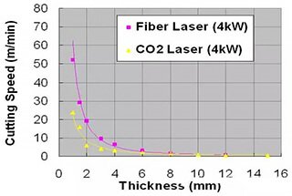
For continuous-wave laser generators, the power of the laser significantly impacts the cutting process. In theory, higher laser power allows for greater cutting speeds.
However, considering the specific characteristics of the tubes, the maximum cutting power is not always the best choice. As cutting power increases, the laser mode also changes, affecting the focus of the laser beam.
Practically, we often opt for a power setting below the maximum to ensure the highest power density at the focal point, thereby ensuring efficiency and quality in laser cutting.
- Effect of Cutting Speed
To achieve good cutting quality, the cutting speed must be within a certain range. If the speed is too slow, excessive heat accumulates on the surface of the tube, enlarging the heat-affected zone, widening the kerf, and burning the cut edges, resulting in a rough surface.
Increasing the speed reduces the average kerf width around the tube’s circumference, and this effect is more pronounced with smaller tube diameters.
As the speed increases, the laser’s interaction time shortens, reducing the total energy absorbed by the tube, decreasing the temperature at the front of the tube, and narrowing the kerf width. If the speed is too fast, incomplete cuts or breaks may occur, affecting the overall cutting quality.
- Effect of Tube Diameter
When laser cutting tubes, the characteristics of the tubes themselves greatly influence the process. For instance, the size of a circular tube’s diameter significantly impacts the quality of the cut.
Studies on laser cutting thin-walled seamless steel tubes have shown that, with constant process parameters, an increase in tube diameter results in a wider kerf.
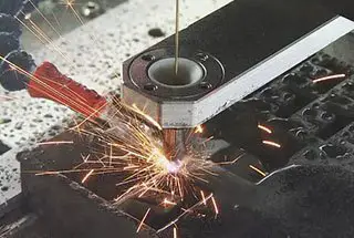
- Type and Pressure of Assist Gas
For cutting non-metallic and some metallic tubes, compressed air or inert gases (such as nitrogen) can be used as assist gases, while for most metallic tubes, active gases (such as oxygen) are preferable.
After selecting the type of assist gas, determining its pressure is also crucial. High pressure is needed when cutting thin-walled tubes at high speeds to prevent slag from adhering to the cut edges.
Conversely, when cutting thicker walls or at slower speeds, the assist gas pressure should be reduced to avoid incomplete cuts. The position of the laser beam’s focal point during tube cutting is also vital.
The focal point should generally be on the surface of the tube being cut; when in the optimal position, the kerf is minimized, cutting efficiency is maximized, and the best cutting outcomes are achieved.