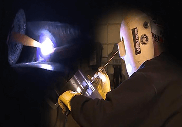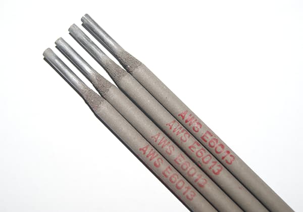
용접 전압 및 전류 선택: 팁
완벽한 용접을 달성하려면 단순한 기술 이상의 것이 필요합니다. 전압과 전류의 상호 작용을 마스터하는 데 달려 있습니다. 이 두 가지 매개 변수는 용접의 생명선이며 다음과 같은 모든 것을 결정합니다.
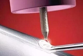
용접이 어떻게 분리된 금속 조각을 하나의 통일된 전체로 변화시키는지 궁금한 적이 있나요? 이 글에서는 용접 조인트의 유형, 기계적 특성 및 설계의 중요한 요소를 살펴보면서 용접 조인트의 매혹적인 세계를 살펴봅니다. 이러한 접합부가 금속 구조물의 강도와 내구성에 어떤 영향을 미치는지 알아보세요.
아크 용접 조인트는 각각 고유한 특성과 특성을 가진 네 개의 서로 다른 영역으로 구성된 복잡한 구조입니다:
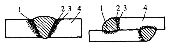
1 - 금속 용접
2 - 녹은 와이어
3 - 열 영향 구역
4 - 기본 자료
용접 프로세스 조인트에 다음과 같은 기계적 특성을 불어넣습니다:
1) 용접 조인트의 이질적인 기계적 성능
용접 중에 발생하는 다양한 야금 공정과 부위마다 영향을 미치는 열 주기 및 변형 주기가 다르기 때문에 이러한 부위의 구조와 특성에 상당한 불균형이 발생합니다. 이로 인해 전체 조인트의 기계적 성능이 이질화됩니다.
2) 용접 접합부의 고르지 않은 응력 분포 및 농도
용접 조인트에 내재된 기하학적 불연속성은 작업 응력의 고르지 않은 분포와 그에 따른 응력 집중으로 이어집니다. 용접 결함이 있거나 용접 이음새 또는 조인트의 모양이 비현실적인 경우 응력 집중이 심해져 조인트 강도, 특히 피로 강도.
3) 잔여 스트레스 용접 중 불균일한 가열로 인한 변형
용접은 국부적인 가열 공정입니다. 동안 아크 용접용접 이음새의 온도는 재료의 끓는점에 도달할 수 있지만, 이음새에서 상온으로 내려가면 온도가 급격히 낮아집니다. 이러한 고르지 않은 온도 필드는 용접부 내에 잔류 응력과 변형을 유발합니다.
4) 용접 조인트의 높은 강성
용접을 통해 이음새와 부품이 일체화되어 리벳이나 수축 조인트에 비해 더 높은 강성을 얻을 수 있습니다.
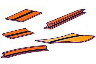
용접 조인트(조인트라고도 함): 용접으로 연결된 조인트입니다.
일반적으로 사용되는 용접 조인트:
버트 조인트, T 조인트, 크로스 조인트, 랩 조인트, 코너 조인트, 에지 조인트, 슬리브 조인트, 베벨 버트 조인트, 플랜지 조인트, 더블-V 버트 조인트 등이 있습니다.
용접 조인트의 기본 유형입니다.
| 이름 | 용접 이음새 형성 | 이름 | 용접 이음새 형성 |
| 엉덩이 관절 |  | 터미널 커넥터 |  |
| T-조인트 |  | 비스듬한 엉덩이 커넥터 | 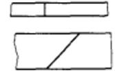 |
| 코너 조인트 | 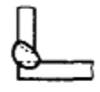 | 플랜지 커넥터 | |
| 무릎 관절 | 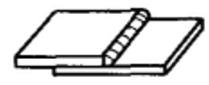 | 밀폐형 버트 커넥터 |
1. 엉덩이 관절
맞대기 접합은 동일한 평면에 위치한 두 공작물의 맞닿는 모서리를 용접하여 형성됩니다. 이 접합 구성은 세련된 디자인, 우수한 하중 지지력, 높은 중량 대비 강도, 효율적인 재료 활용으로 인해 다양한 용접 구조물에 널리 채택되고 있습니다.
버트 조인트의 인기는 용접부를 통해 직접 힘을 전달할 수 있어 다른 조인트 유형에 비해 응력 분포가 더 균일하기 때문입니다. 이러한 특성으로 인해 압력 용기, 파이프라인, 구조용 강철 프레임워크와 같이 주기적으로 하중이 가해지거나 피로가 발생하기 쉬운 환경에 특히 적합합니다.
그러나 엣지 투 엣지 연결의 특성상 결합 표면의 준비와 정렬에 엄격한 요구 사항이 적용됩니다. 두꺼운 재료에 대한 베벨링을 포함한 정밀한 모서리 준비와 엄격한 맞춤 공차 유지는 완전한 관통을 보장하고 용접 결함의 위험을 최소화하는 데 매우 중요합니다.
용접 생산에서 맞대기 접합의 용접 비드는 일반적으로 모재 표면 위로 약간 볼록하게 튀어나오는 프로파일을 나타냅니다. 이 보강재는 추가적인 강도를 제공할 수 있지만 기하학적 불연속성을 생성하기도 합니다. 이러한 불균일한 표면은 용접 금속과 모재 사이의 전이 영역인 용접 토에 응력 집중을 유발할 수 있습니다. 이 문제를 완화하기 위해 연삭 또는 기계 가공과 같은 용접 후 처리를 통해 표면을 평평하게 만들 수 있으며, 특히 피로 저항이나 공기 역학적 특성이 중요한 응용 분야에서는 더욱 그렇습니다.
자동화된 레이저 용접 또는 전자빔 용접과 같은 최신 용접 기술은 왜곡을 최소화하고 열 영향 영역을 좁히면서 고품질 맞대기 접합부를 생산할 수 있어 접합부의 기계적 특성과 전반적인 구조적 무결성을 더욱 향상시킬 수 있습니다.

2. T-관절
T 조인트(또는 크로스 조인트)는 필렛 용접을 사용하여 수직 부재를 연결하여 문자 "T"와 유사한 구성을 만들어 형성됩니다. 이 다목적 조인트는 다방향의 힘과 토크를 견딜 수 있어 다양한 구조물에서 필수적으로 사용됩니다. T 조인트는 주로 박스 구조, 압력 용기 제조(튜브와 쉘 연결 등), 맨홀 보강 링을 용기 본체에 부착하는 데 사용됩니다.
T-조인트의 기하학적 구조는 응력 분포에 있어 독특한 문제를 야기합니다. 용접 이음새에서 모재로의 갑작스러운 전환은 외부 하중 하에서 힘의 흐름에 상당한 왜곡을 일으켜 매우 불균일하고 복잡한 응력장을 생성합니다. 이러한 현상은 피로 파괴가 발생하기 쉬운 중요한 영역인 필렛 용접의 루트 및 토우에 상당한 응력 집중으로 이어집니다.
이러한 스트레스 집중을 완화하고 관절 성능을 향상시키기 위해 몇 가지 전략을 사용할 수 있습니다:
T 조인트를 설계하고 제작할 때 엔지니어는 재료 선택, 용접 매개변수, 잠재적 하중 시나리오 등의 요소를 신중하게 고려하여 최적의 조인트 성능과 사용 수명을 보장해야 합니다.
3. 무릎 관절
랩 조인트는 두 개의 플레이트를 겹친 다음 끝 또는 측면에 필렛 용접을 수행하거나 플러그 또는 그루브 용접을 추가하여 만듭니다. 랩 조인트에서 두 플레이트 중심선의 정렬이 잘못되어 하중을 받으면 추가 굽힘 모멘트가 발생하여 다음과 같은 영향을 줄 수 있습니다. 용접 강도.
따라서 랩 조인트는 일반적으로 보일러 및 압력 용기의 주요 압력 베어링 요소에는 사용되지 않습니다.
랩 조인트로 인해 부품의 모양이 크게 변경되면 맞대기 조인트에 비해 응력 집중이 더 복잡해져 조인트 전체에 걸쳐 응력 분포가 매우 고르지 않게 됩니다.
랩 조인트 내에서 오버랩 필렛 용접에 작용하는 다양한 응력 방향에 따라 이러한 용접은 정면, 측면 또는 대각선으로 분류할 수 있습니다. 필렛 용접.

랩 조인트에는 끝 또는 측면에 쌓인 두 개의 강판을 용접하는 것 외에도 홈 용접과 플러그 용접(둥근 구멍과 길쭉한 구멍)도 포함됩니다. 그루브 용접 랩 조인트의 구조는 그림에 나와 있습니다.
먼저 연결할 공작물을 홈에 펀칭한 다음 홈을 용접 금속으로 채웁니다. 그루브 용접의 단면은 직사각형이며 너비는 연결된 구성 요소 두께의 두 배입니다. 그루브의 길이는 랩 길이보다 약간 짧아야 합니다.

플러그 용접에는 다음이 포함됩니다. 드릴링 결합할 플레이트에 구멍을 뚫고 홈 용접으로 홈을 대체한 후 용접 금속을 사용하여 이 구멍을 메워 두 플레이트를 연결합니다. 플러그 용접은 그림과 같이 원형 홀 플러그 용접과 길쭉한 홀 플러그 용접의 두 가지 유형으로 나눌 수 있습니다.

4. 코너 조인트
코너 조인트는 두 개의 플레이트가 모서리에서 특정 각도로 용접될 때 형성됩니다. 코너 조인트는 일반적으로 박스 구조, 새들 파이프 조인트 및 원통형 몸체와의 연결에 사용됩니다. 소형 보일러의 연통과 엔드 캡 사이의 연결도 이 형태를 취합니다.
T 조인트와 마찬가지로 단면 코너 조인트는 역방향 굽힘 모멘트에 대한 저항이 매우 낮습니다. 플레이트가 매우 얇거나 구조가 중요하지 않은 경우가 아니라면 일반적으로 양면 용접을 위해 베벨을 만들어야 하며, 그렇지 않으면 품질을 보장할 수 없습니다.
조인트 유형을 선택할 때는 주로 제품의 구조와 응력 조건 및 처리 비용과 같은 요소를 고려하세요.
예를 들어
버트 조인트는 응력을 고르게 분산하고 금속을 절약할 수 있어 널리 사용됩니다. 하지만 버트 조인트는 정확한 절단 치수와 조립이 필요합니다.
T 조인트는 대부분 경미한 전단 응력을 견디거나 단순히 연결 용접 역할을 합니다.
랩 조인트는 높은 조립 정밀도가 필요하지 않고 조립이 쉽지만 하중 지지력이 낮기 때문에 일반적으로 중요하지 않은 구조에 사용됩니다.
용접 조인트 설계에서 용접 품질, 용접 크기, 용접 위치, 공작물 두께, 기하학적 치수 및 작업 조건에 대한 요구 사항은 다음을 선택하는 데 있어 다양성을 결정합니다. 용접 방법 공정을 공식화합니다. 용접 조인트의 합리적인 설계와 선택은 용접부와 전체 철골 구조의 강도를 보장할 뿐만 아니라 생산 공정을 간소화하고 제조 비용을 절감합니다.
용접 조인트 설계 및 선택의 주요 요소:
표 1-2: 용접 조인트 형태의 비교 설계
| 공동 설계의 원칙 | 결함이 발생하기 쉬운 설계 | 개선된 디자인 |
| 전면을 늘리세요. 앵글 용접 |  |  |
| 용접 및 검사가 용이하도록 설계된 용접 이음새 위치 |  |  |
| 랩 용접 이음새의 응력 집중을 줄이려면 특정 응력 완화 기능이 있는 이음새로 설계해야 합니다. |  |  |
| 보강 리브의 날카로운 모서리를 잘라냅니다. |  |  |
| 용접 이음새는 분산되어야 합니다. |  |  |
| 교차 용접 이음새 방지 |  |  |
| 용접 이음새는 대칭 위치의 중립 축 또는 그 부근에 설계되어야 합니다. |  |  |
| 굽힘이 발생하는 용접 이음새는 용접되지 않은 압축면이 아닌 인장면을 기준으로 설계해야 합니다. |  |  |
| 용접 이음새는 응력이 집중되는 곳에 배치하지 마세요. |  |  |
| 용접 이음새는 응력이 가장 큰 부분을 피해야 합니다. |  |  |
| 가공 표면에 용접 이음새가 없어야 합니다. | 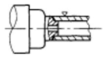 |  |
| 자동 용접 이음새의 위치는 용접 장비의 조정과 공작물 뒤집기 횟수를 최소화할 수 있는 위치로 설계해야 합니다. |  |  |
용접 이음새는 부품을 용접한 후 형성되는 이음새입니다.
카테고리:
1. 공간적 위치에 따라 평면 용접 이음새, 수평 용접 이음새, 수직 용접 이음새, 오버헤드 용접 이음새로 나눌 수 있습니다.
2. 접합 방식에 따라 맞대기 용접 이음새, 코너 용접 이음새, 플러그 용접 이음새로 분류할 수 있습니다.
3. 연속성에 따라 연속 용접 이음새와 간헐적 용접 이음새로 분류할 수 있습니다.
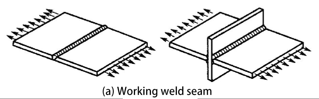
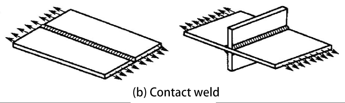
4. 하중 지지력에 따라 작업용접 이음새와 접촉용접 이음새로 나눌 수 있습니다.
용접 심은 용접 조인트의 중요한 구성 요소입니다. 용접 심의 기본 형태는 맞대기 조인트 용접 심과 코너 조인트 용접 심입니다.
1. 맞대기 용접 솔기:
맞대기 용접 이음새는 두 부품 사이의 접합부를 따라 형성됩니다. 홈이 없는 홈(또는 I자형 홈) 또는 홈이 있는 구성일 수 있습니다. 용접 이음새의 표면 모양은 볼록하거나 표면과 평평할 수 있습니다.
2. 모서리 용접 이음새:

작업용 용접 이음새(하중지지 용접 이음새라고도 함)
용접 이음새는 용접된 부품과 직렬로 연결되어 주로 하중을 견디는 용접 이음새입니다. 이러한 이음새가 파열되면 철골 구조물은 즉시 심각한 손상을 입게 됩니다.
접촉 용접 이음새(비내하중 용접 이음새라고도 함)
이는 두 개 이상의 용접 부품을 평행하게 통합하는(즉, 연결성을 제공하는) 용접 이음새입니다. 이러한 이음새는 직접적으로 하중을 견디지 않으며 작동 중에 최소한의 힘을 받습니다. 이러한 이음새가 파열되더라도 구조가 즉시 파손되지는 않습니다.
1. 그루브의 유형
홈은 설계 또는 공정 요구 사항에 따라 공작물의 용접 대상 부위에 특정 기하학적 모양을 가공하여 형성된 홈입니다.
그루브 준비:
기계적 방법, 화염 또는 전기 아크를 사용하여 홈을 가공하는 과정입니다.
그루브 준비의 목적:
(1) 아크가 용접 이음새의 뿌리 깊숙이 침투하여 완전한 융합을 이루고 최적의 용접 이음새 형성을 달성하며 슬래그 제거가 용이하도록 합니다.
(2) 대상 합금강홈은 모재와 필러 금속의 비율(즉, 용융 비율)도 조정합니다.
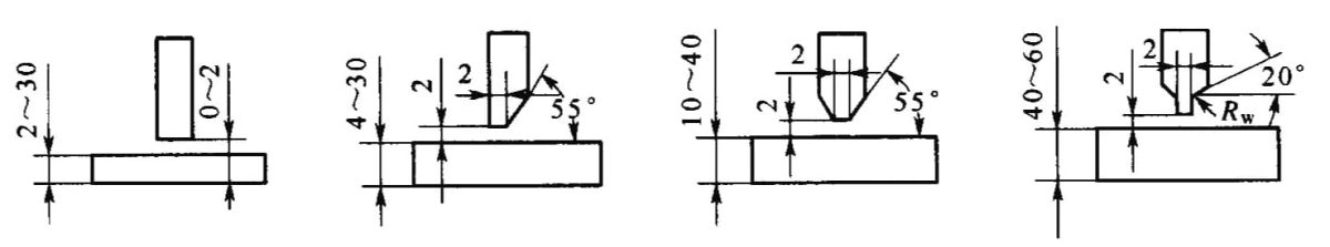
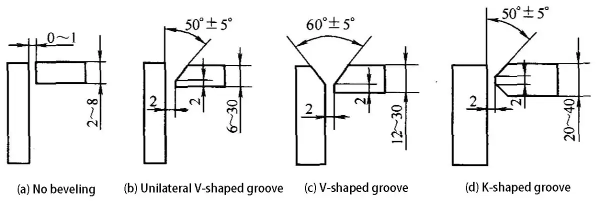
플레이트의 두께에 따라 맞대기 용접 이음새의 용접 모서리를 롤링, 스퀘어 또는 V자형, X자형, K자형 및 U자형 홈으로 가공할 수 있습니다.

(2) 공작물의 두께, 구조 및 하중지지 조건에 따라 코너 조인트 및 T 조인트의 홈 모양은 I 형, 모서리가 뭉툭한 단면 V 형 및 K 형으로 나눌 수 있습니다.

a) I자형
b) 단면 V자형(모서리가 뭉툭한 경우)
c) K자형(가장자리가 뭉툭한 경우)
2. 그루브 디자인 원칙
홈의 형태와 치수는 주로 철골 구조물의 두께, 선택한 용접 방법, 용접 위치 및 용접 공정에 따라 선택 및 설계됩니다. 디자인은 다음과 같아야 합니다:
1) 용접 이음새의 충전재 양을 최소화합니다;
2) 좋은 전시 용접성;
3) 홈 모양이 가공하기 쉬운지 확인합니다;
4) 용접 변형의 조정을 용이하게 합니다;
일반적으로 전극 아크 용접을 사용하여 최대 6mm 두께의 공작물을 용접하거나 최대 14mm 두께의 공작물을 자동 용접하는 경우 홈 준비 없이도 적격 용접 심을 얻을 수 있습니다.
그러나 필러 금속이 용접 풀을 채우고 완전한 융합을 보장하기 위해 플레이트 사이에 간격을 유지해야 합니다. 만약 강판 두께가 위에서 언급한 두께를 초과하면 아크가 플레이트를 관통할 수 없으므로 홈 준비를 고려해야 합니다.
설계를 정밀하고 정확하게 제작하기 위해 엔지니어는 상세 설계 도면과 종합 사양 문서를 통해 구조물과 제품의 기술 사양을 포괄적으로 전달해야 합니다.
용접 접합부의 경우 설계자는 주로 표준화된 용접 심볼과 용접 공정 코드를 활용합니다. 전통적인 기술 제도 방법을 사용할 수 있지만, 복잡한 용접 공정 요구 사항과 복잡한 접합부에 대한 고려 사항을 그래픽 또는 텍스트로 상세히 설명하는 것은 지나치게 번거롭고 오해의 소지가 있을 수 있습니다.
따라서 표준화된 기호와 코드를 구현하는 것은 용접 조인트의 다음과 같은 중요한 측면을 명확하게 지정하는 데 매우 중요합니다:
이러한 표준화된 표현은 설계부터 제작까지의 워크플로우를 간소화할 뿐만 아니라 커뮤니케이션 오류를 최소화하고 생산성을 높이며 다양한 제조 환경 전반에서 일관된 품질을 보장합니다. 또한 글로벌 제조 운영 및 품질 보증에 필수적인 AWS A2.4 또는 ISO 2553과 같은 국제 용접 표준을 보다 쉽게 준수할 수 있도록 지원합니다.
이음새 심볼을 용접합니다: 도면에 표시된 기호는 용접 이음새의 형태, 크기 및 방법을 나타냅니다.
이는 GB/T324-1998 "용접 이음새의 상징적 표현"(금속 융착 용접 및 저항 용접에 적용 가능) 및 GB/T5185-1999 "금속 용접의 표현 코드"에 의해 규제됩니다. 브레이징 도면의 메서드.
용접 이음새 기호는 다음으로 구성됩니다:
기본 기호: 이 기호는 용접 이음새의 단면 모양을 나타내며, 용접 이음새의 단면 모양을 근사화합니다.
| 용접 이음새 이름 | 용접 이음새의 단면 모양입니다. | 기호 |
| I자형 용접 이음새 |  |  |
| V자형 용접 이음새 | 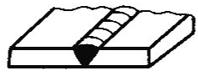 |  |
| 무딘 모서리의 V자형 용접 이음새 |  |  |
| 단면 V자형 용접 이음새 | 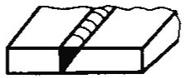 |  |
| 무딘 모서리의 단면 V자형 용접 이음새 |  | |
| 무딘 모서리의 U자형 용접 이음새 | 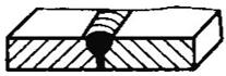 |  |
| 씰링 용접 이음새 |  | |
| 필렛 용접 | 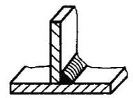 |  |
| 플러그 용접 또는 그루브 용접 | 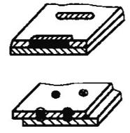 |  |
| 플레어-V 용접 |  |  |
| 스폿 용접 |  |  |
| 심 용접 | 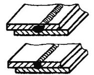 |  |
보조 기호: 이 기호는 용접 심의 표면 형상 특성에 대한 추가 요구 사항을 나타냅니다. 보충 기호는 일반적으로 용접 심의 표면 모양에 대한 특별한 요구 사항이 있을 때 기본 용접 심 심볼과 함께 사용됩니다.
| 이름 | 지원 용접 기술 | 기호 | 지침 |
| 플랫 기호 | 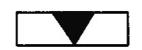 | 플러시 용접 표면을 나타냅니다. | |
| 오목한 기호 | 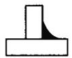 | 오목한 용접 표면을 나타냅니다. | |
| 볼록 기호 | 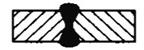 | 볼록한 용접 표면을 나타냅니다. |
용접 보강 기호: 용접 이음새의 특정 특성을 자세히 설명하는 데 사용되는 기호입니다.
| 이름 | 양식 | 기호 | 표시 |
| 기호와 패드 |  | 용접 이음새 하단에 백킹 스트립이 있음을 나타냅니다. | |
| 3면 용접 기호 |  |  | 3면 용접 이음새와 개구부의 방향을 제안합니다. |
| 경계 용접 기호 |  |  | 공작물을 둘러싼 용접 이음새를 상징합니다. |
| 필드 기호 |  | 현장 또는 건설 현장에서 수행되는 용접을 나타냅니다. | |
| 꼬리 기호 |  | 리드 라인 기호의 꼬리 끝은 용접 방법 및 이와 유사한 표기에 대해 GB5185-1999를 참조할 수 있습니다." |
용접 심 치수 기호: 홈 및 용접 이음새 피처의 치수를 나타내는 데 사용되는 기호입니다.
| 기호 | 이름 | 회로도 |
| σ | 시트 두께 |  |
| c | 용접 솔기 폭 | 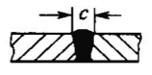 |
| b | 루트 갭 |  |
| K | 용접 발가락 높이 | 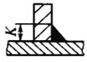 |
| p | 무딘 가장자리 높이 |  |
| d | 용접 지점 직경 |  |
| a | 홈 각도 | 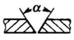 |
| h | 용접 보강 |  |
| s | 유효 용접 두께동일 용접 조인트 | 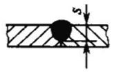 |
| N | 수량 기호 |  |
| e | 용접 간격 |  |
| l | 용접 길이 |  |
| R | 루트 반경 |  |
| H | 홈 높이 |  |
리더 라인: 화살표 지시선, 두 개의 참조선(수평선)(실선과 점선), 꼬리 부분으로 구성됩니다.

용접 방법에 대한 주석 및 텍스트 설명을 간소화하기 위해 국가 표준 GB/T 5185-1999에 따라 아라비아 숫자로 표시된 금속 용접, 브레이징 등 다양한 용접 방법을 나타내는 코드를 활용할 수 있습니다.
용접 방법 주석은 가이드 라인 끝에 있습니다.
| 이름 | 용접 방법 |
| 아크 용접 | 1 |
| 차폐 메탈 아크 용접 | 111 |
| 서브머지드 아크 용접 | 12 |
| 금속 불활성 가스 용접 (MIG) | 131 |
| 텅스텐 불활성 가스 용접(TIG) | 141 |
| 압력 용접 | 4 |
| 초음파 용접 | 41 |
| 마찰 용접 | 42 |
| 확산 용접 | 45 |
| 폭발 용접 | 441 |
| 저항 용접 | 2 |
| 스폿 용접 | 21 |
| 심 용접 | 22 |
| 플래시 용접 | 24 |
| 가스 용접 | 3 |
| 옥시-아세틸렌 용접 | 311 |
| 옥시-프로판 용접 | 312 |
| 기타 용접 방법 | 7 |
| 레이저 용접 | 751 |
| 전자 빔 | 76 |
용접의 도식적 표현
국가 표준 GB/Tl2212-1990 "기술 도면 - 치수, 비율 및 단순화 된 표현에 따르면 용접 기호"도면에서 용접부를 단순화된 방식으로 묘사해야 하는 경우 보기, 단면도 또는 단면도, 심지어 설명 목적으로 축척도를 사용하여 표현할 수 있습니다.
일반적으로 도면당 한 가지 유형의 표현만 허용됩니다.


(a) 용접 단면도의 도면 작성 방법
(b) 용접 이음새 단면도 그리기 방법
(c) 용접 프로파일 그리기 방법


국가 표준 GB/T324-1988, GB/T5185-1999 및 GB/T12212-1990은 각각 용접 기호 및 용접 방법 코드에 대한 주석 방법을 규정하고 있습니다.
(1) 용접 기호 및 용접 방법 코드는 가이드 라인과 관련 규정을 통해 정확하고 명확하게 표현할 수 있습니다.
(2) 용접 부위에 주석을 달 때는 먼저 기준선 위 또는 아래에 기본 용접 부위에 주석을 달고 다른 기호는 규정된 대로 해당 위치에 주석을 달아야 합니다.
(3) 일반적으로 용접에 대한 화살표 선의 위치에 대한 구체적인 요구 사항은 없지만, V자형, 단면 V자형, J자형 등의 용접에 주석을 달 때 화살표는 홈이 있는 공작물을 가리켜야 합니다.
(4) 필요한 경우 화살표 선을 한 번 구부릴 수 있습니다.
(5) 가상의 기준선은 실제 기준선 위 또는 아래에 그릴 수 있습니다.
(6) 기준선은 일반적으로 도면의 하단 가장자리와 평행해야 하지만 특수한 조건에서는 하단 가장자리와 수직이 될 수도 있습니다.
(7) 용접부와 화살표선이 접합부의 같은 면에 있는 경우 기본 용접 기호는 실제 기준선 쪽에 주석을 달고, 반대로 용접부와 화살표선이 접합부의 같은 면에 없는 경우 기본 용접 기호는 가상의 기준선 쪽에 주석을 답니다.
필요한 경우 기본 용접 기호에 크기 기호 및 데이터를 첨부할 수 있습니다.

주석 원칙:
1) 용접 심 단면의 치수는 기본 기호의 왼쪽에 무딘 모서리 높이 p, 홈 높이 H, 용접 각도 크기 K, 용접 심 잔류 높이 h, 용접 심 유효 두께 S, 루트 반경 R, 용접 심 폭 C, 용접 너겟 직경 d와 같이 표시되어 있습니다.
2) 용접 심 길이 방향의 치수는 기본 기호의 오른쪽에 용접 심 길이 L, 용접 심 간격 e, 동일한 용접 심 수 n과 같이 표시되어 있습니다.
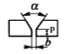
3) 홈 각도 α, 홈 면 각도 β, 루트 간격 b 및 기타 치수는 기본 기호의 위쪽 또는 아래쪽에 표시됩니다.
4) 동일한 용접 이음새의 개수를 나타내는 기호는 꼬리 끝에 표시됩니다.
5) 표시할 차원이 많고 구분이 쉽지 않은 경우 데이터 앞에 해당 차원 기호를 추가할 수 있습니다.
| 이름 | 회로도 | 라벨링 |
| 버트 용접 솔기 |  |  |
 |  | |
| 간헐적 필렛 용접 이음새 |  |  |
| 엇갈린 간헐적 필렛 용접 이음새 |  |  |
| 스폿 용접 솔기 |  |  |
| 솔기 용접 솔기 |  |  |
| 플러그 용접 이음새 또는 그루브 용접 이음새 |  |  |
GB/T12212-1990에서는 특정 상황에서 용접 조인트에 대한 간소화된 주석 방법도 규정하고 있습니다.


MachineMFG의 창립자인 저는 10년 넘게 금속 가공 산업에 종사해 왔습니다. 폭넓은 경험을 통해 판금 제조, 기계 가공, 기계 공학 및 금속용 공작 기계 분야의 전문가가 될 수 있었습니다. 저는 이러한 주제에 대해 끊임없이 생각하고, 읽고, 글을 쓰면서 제 분야에서 선두를 유지하기 위해 끊임없이 노력하고 있습니다. 저의 지식과 전문성을 귀사의 비즈니스에 자산으로 활용하세요.