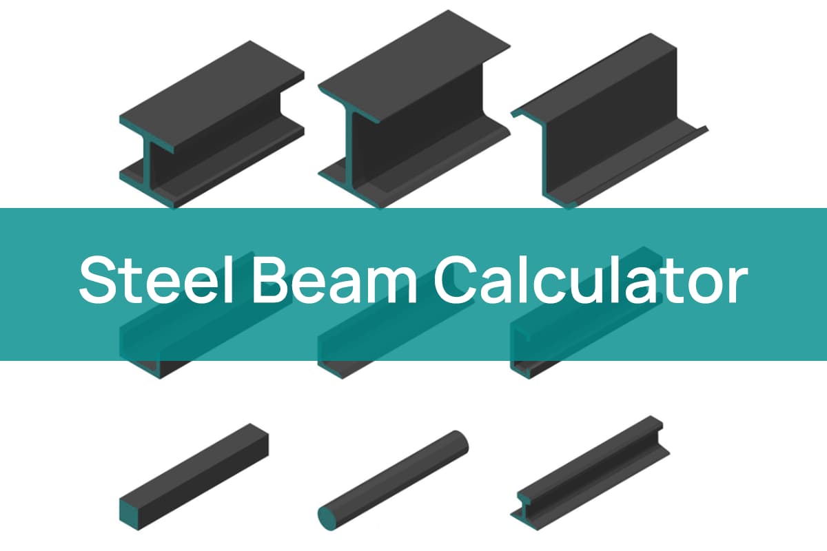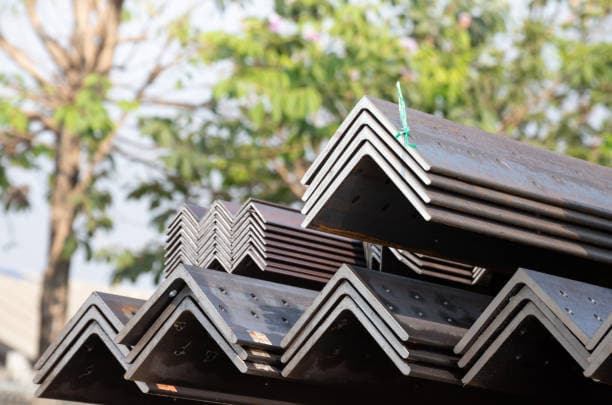
Have you ever wondered about the hidden hero behind modern construction marvels? L-shaped steel, also known as angle steel, is a versatile material that plays a crucial role in large-scale projects like shipbuilding. In this article, we’ll explore the unique properties and advantages of L-shaped steel, as explained by an experienced mechanical engineer. Discover how this innovative profile is revolutionizing the industry and enhancing the efficiency of modern structures.

L-shaped steel, also known as angle steel or angle iron, is a versatile structural profile widely used in various industries, including shipbuilding, construction, and manufacturing. Its cross-section resembles the letter “L”, consisting of two perpendicular legs or flanges.
In large-scale ship construction, L-shaped steel has gained prominence due to its superior structural properties compared to traditional flat steel profiles:
The adoption of L-shaped steel in modern shipbuilding represents an evolution in naval architecture, balancing structural integrity with economic considerations and ease of fabrication.

L-shaped steel, also known as angle steel or angle iron, is primarily categorized into two main types: equal angle steel and unequal angle steel. These structural elements are widely used in various industries due to their versatility and strength.
Equal Angle Steel:
This type features two legs of equal length forming a 90-degree angle. The cross-section resembles a perfect “L” shape, with both legs having identical dimensions. Equal angle steel is commonly used in applications where uniform load distribution is required.
Unequal Angle Steel:
This category is characterized by legs of different lengths, while still maintaining a 90-degree angle. Unequal angle steel can be further subdivided into two distinct subtypes:
a. Equal Thickness on Unequal Sides:
In this configuration, the legs have different lengths but maintain a uniform thickness throughout. This design offers flexibility in load-bearing capabilities while simplifying fabrication processes.
b. Unequal Thickness on Unequal Sides:
This subtype features legs of different lengths and varying thicknesses. This configuration allows for optimized weight distribution and customized strength characteristics, making it suitable for specialized engineering applications.
The choice between these types depends on specific project requirements, load-bearing needs, and fabrication considerations. Each type offers unique advantages in terms of strength-to-weight ratio, cost-effectiveness, and ease of installation, making L-beam steel a versatile option in structural engineering and metal fabrication.
Hot-rolled L-beam steel, also known as angle steel, is manufactured according to the dimensional, shape, weight, and allowable deviation specifications outlined in the GB/T 706-2008 standard. Standard lengths for hot-rolled L-beam steel typically range from 5 meters to 19 meters, catering to various industrial applications.
In the market, L-beam steel is commonly supplied based on either actual weight or theoretical weight. The industry standard allows for a deviation between the theoretical and actual weight of L-beam steel, typically ranging from ±3% to ±5%. This tolerance accounts for minor variations in the manufacturing process while ensuring consistent quality and performance.
To facilitate accurate material estimation and project planning, we provide an L-beam steel weight calculator below. This tool enables you to quickly determine the weight of L-beam steel based on its dimensions and length, considering the standard density of steel used in structural applications.
When using this calculator, it’s important to note that the results represent the theoretical weight. For precise weight calculations, especially for large orders or critical applications, it’s advisable to consult with the manufacturer or supplier for the most up-to-date weight tolerances and any specific variations in their production process.
Understanding the weight of L-beam steel is crucial for various aspects of construction and manufacturing, including:
By accurately calculating the weight of L-beam steel, engineers, contractors, and project managers can optimize material usage, improve cost efficiency, and ensure structural integrity in their designs and constructions.
Related Tool: Steel Weight Calculator
Theoretical weight table of equilateral angle steel
The following table provides the theoretical weights of equal angle steel beams, also known as L-beams or angle iron. These values are calculated based on standard dimensions and material density, offering a quick reference for estimating material requirements in various construction and fabrication projects.
| Spec.(Length*Thickness) mm | Weight (kg/m) |
| 20*3 | 0.89 |
| 20*4 | 1.15 |
| 25*3 | 1.12 |
| 25*4 | 1.46 |
| 30*3 | 1.37 |
| 30*4 | 1.79 |
| 36*3 | 1.66 |
| 36*4 | 2.16 |
| 36*5 | 2.65 |
| 40*3 | 1.85 |
| 40*4 | 2.42 |
| 40*5 | 2.98 |
| 45*3 | 2.09 |
| 45*4 | 2.74 |
| 45*5 | 3.37 |
| 45*6 | 3.99 |
| 50*3 | 2.33 |
| 50*4 | 3.06 |
| 50*5 | 3.77 |
| 50*6 | 4.46 |
| 56*3 | 2.62 |
| 56*4 | 3.45 |
| 56*5 | 4.25 |
| 56*8 | 6.57 |
| 63*4 | 3.91 |
| 63*5 | 4.82 |
| 63*6 | 5.72 |
| 63*8 | 7.47 |
| 63*10 | 9.15 |
| 70*4 | 4.37 |
| 70*5 | 5.4 |
| 70*6 | 6.41 |
| 70*7 | 7.4 |
| 70*8 | 8.37 |
| 75*5 | 5.82 |
| 75*6 | 6.91 |
| 75*7 | 7.98 |
| 75*8 | 9.03 |
| 75*10 | 11.09 |
| 80*5 | 6.21 |
| 80*6 | 7.38 |
| 80*7 | 8.53 |
| 80*8 | 9.66 |
| 80*10 | 11.87 |
| 90*6 | 8.35 |
| 90*7 | 9.66 |
| 90*8 | 10.95 |
| 90*10 | 13.48 |
| 90*12 | 15.94 |
| 100*6 | 9.37 |
| 100*7 | 10.83 |
| 100*8 | 12.28 |
| 100*10 | 15.12 |
| 100*12 | 17.9 |
| 100*14 | 20.61 |
| 100*16 | 23.26 |
| 110*7 | 11.93 |
| 110*8 | 13.53 |
| 110*10 | 16.69 |
| 110*12 | 19.78 |
| 110*14 | 22.81 |
| 125*8 | 15.5 |
| 125*10 | 19.13 |
| 125*12 | 22.7 |
| 125*14 | 26.19 |
| 140*10 | 21.49 |
| 140*12 | 25.52 |
| 140*14 | 29.49 |
| 140*16 | 33.39 |
| 160*10 | 24.73 |
| 160*12 | 29.39 |
| 160*14 | 33.99 |
| 160*16 | 38.52 |
| 180*12 | 33.16 |
| 180*14 | 38.38 |
| 180*16 | 43.54 |
| 180*18 | 48.63 |
| 200*14 | 42.89 |
| 200*16 | 48.68 |
| 200*18 | 54.4 |
| 200*20 | 60.06 |
| 200*24 | 71.17 |
Theoretical weight table of unequal angle steel
| Spec.(Length*Thickness) mm | Weight (kg/m) |
| 25*16*3 | 0.91 |
| 25*16*4 | 1.18 |
| 32*20*3 | 1.17 |
| 32*20*4 | 1.52 |
| 40*25*3 | 1.48 |
| 40*25*4 | 1.94 |
| 45*28*4 | 1.69 |
| 45*28*5 | 2.2 |
| 50*32*3 | 1.91 |
| 50*32*4 | 2.49 |
| 56*36*3 | 2.15 |
| 56*36*4 | 2.82 |
| 56*36*5 | 3.47 |
| 63*40*4 | 3.19 |
| 63*40*5 | 3.92 |
| 63*40*6 | 4.64 |
| 63*40*7 | 10 |
| 70*45*4 | 3.57 |
| 70*45*5 | 4.4 |
| 70*45*6 | 5.22 |
| 70*45*7 | 6.01 |
| 75*50*5 | 4.81 |
| 75*50*6 | 5.7 |
| 75*50*8 | 7.43 |
| 75*50*10 | 9.1 |
| 80*50*5 | 5 |
| 80*50*6 | 5.93 |
| 80*50*7 | 6.85 |
| 80*50*8 | 7.75 |
| 90*56*5 | 5.66 |
| 90*56*6 | 6.72 |
| 90*56*7 | 7.76 |
| 90*56*8 | 8.78 |
| 100*63*6 | 7.55 |
| 100*63*7 | 8.72 |
| 100*63*8 | 9.88 |
| 100*63*10 | 12.1 |
| 100*80*6 | 8.35 |
| 100*80*7 | 9.66 |
| 100*80*8 | 10.9 |
| 100*80*10 | 13.5 |
| 110*70*6 | 8.35 |
| 110*70*7 | 9.66 |
| 110*70*8 | 10.9 |
| 110*70*10 | 13.5 |
| 125*80*7 | 11.1 |
| 125*80*8 | 12.6 |
| 125*80*10 | 15.5 |
| 125*80*12 | 18.3 |
| 140*90*8 | 14.2 |
| 140*90*10 | 17.5 |
| 140*90*12 | 20.7 |
| 140*90*14 | 23.9 |
| 160*100*10 | 19.9 |
| 160*100*12 | 23.6 |
| 160*100*14 | 27.2 |
| 160*100*16 | 30.8 |
| 180*110*10 | 22.3 |
| 180*110*12 | 26.5 |
| 180*110*14 | 30.6 |
| 180*110*16 | 34.6 |
| 200*125*12 | 29.8 |
| 200*125*14 | 34.4 |
| 200*125*16 | 39 |
| 200*125*18 | 43.6 |
Note: These weights are theoretical and may vary slightly due to manufacturing tolerances and specific material grades. Always consult official product specifications for precise values when critical to design or application. The weight calculations assume a standard steel density of 7.85 g/cm³.
Key points to consider when using this chart:
When working with angle steel, consider factors such as connection design, galvanization requirements (if applicable), and compatibility with other structural elements to ensure optimal performance and longevity of the fabricated structure.


