Curious about the capabilities of laser cutting? In this comprehensive guide, we’ll dive into the world of laser cutting speeds and thicknesses for various metals. Our expert mechanical engineer will walk you through a detailed chart, providing valuable insights and comparisons across different laser powers and materials. Get ready to expand your knowledge and discover the incredible potential of laser cutting technology!

Laser cutting is a highly efficient and precise method for cutting various metals. The cutting speed and thickness capabilities of a laser cutter depend on several factors, including the laser power, type of metal, and material thickness. This article provides a comprehensive laser cutting thickness and speed chart for lasers ranging from 500W to 30kW, covering mild steel, stainless steel, and aluminum.
Key Takeaways
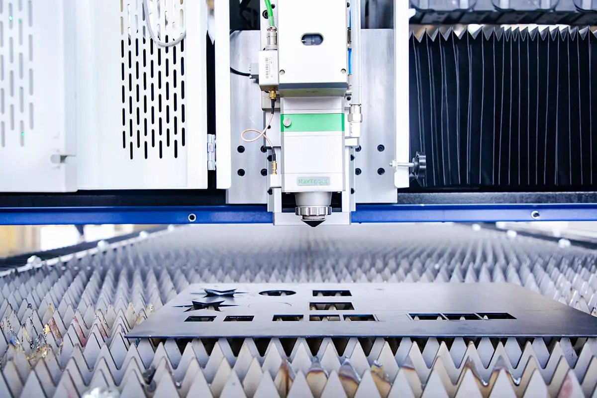
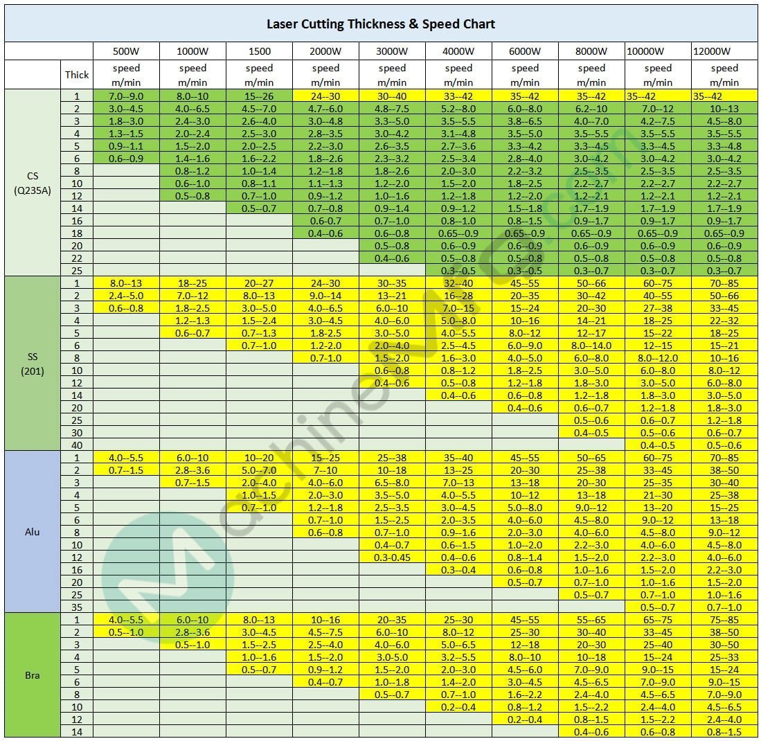
The following chart presents the cutting speeds (in meters per minute) for mild steel (Q235A), stainless steel (201), and aluminum at various thicknesses, using lasers ranging from 500W to 12kW.
Unit: m/min
| Metals | 500W | 1000W | 1500 | 2000W | 3000W | 4000W | 6000W | 8000W | 10kW | 12kW | |
|---|---|---|---|---|---|---|---|---|---|---|---|
| Thickness | speed | speed | speed | speed | speed | speed | speed | speed | speed | speed | |
| Mild Steel (Q235A) | 1 | 7.0–9.0 | 8.0–10 | 15–26 | 24–30 | 30–40 | 33–42 | 35–42 | 35–42 | 35–42 | 35–42 |
| 2 | 3.0–4.5 | 4.0–6.5 | 4.5–7.0 | 4.7–6.0 | 4.8–7.5 | 5.2–8.0 | 6.0–8.0 | 6.2–10 | 7.0–12 | 10–13 | |
| 3 | 1.8–3.0 | 2.4–3.0 | 2.6–4.0 | 3.0–4.8 | 3.3–5.0 | 3.5–5.5 | 3.8–6.5 | 4.0–7.0 | 4.2–7.5 | 4.5–8.0 | |
| 4 | 1.3–1.5 | 2.0–2.4 | 2.5–3.0 | 2.8–3.5 | 3.0–4.2 | 3.1–4.8 | 3.5–5.0 | 3.5–5.5 | 3.5–5.5 | 3.5–5.5 | |
| 5 | 0.9–1.1 | 1.5–2.0 | 2.0–2.5 | 2.2–3.0 | 2.6–3.5 | 2.7–3.6 | 3.3–4.2 | 3.3–4.5 | 3.3–4.5 | 3.3–4.8 | |
| 6 | 0.6–0.9 | 1.4–1.6 | 1.6–2.2 | 1.8–2.6 | 2.3–3.2 | 2.5–3.4 | 2.8–4.0 | 3.0–4.2 | 3.0–4.2 | 3.0–4.2 | |
| 8 | 0.8–1.2 | 1.0–1.4 | 1.2–1.8 | 1.8–2.6 | 2.0–3.0 | 2.2–3.2 | 2.5–3.5 | 2.5–3.5 | 2.5–3.5 | ||
| 10 | 0.6–1.0 | 0.8–1.1 | 1.1–1.3 | 1.2–2.0 | 1.5–2.0 | 1.8–2.5 | 2.2–2.7 | 2.2–2.7 | 2.2–2.7 | ||
| 12 | 0.5–0.8 | 0.7–1.0 | 0.9–1.2 | 1.0–1.6 | 1.2–1.8 | 1.2–2.0 | 1.2–2.1 | 1.2–2.1 | 1.2–2.1 | ||
| 14 | 0.5–0.7 | 0.7–0.8 | 0.9–1.4 | 0.9–1.2 | 1.5–1.8 | 1.7–1.9 | 1.7–1.9 | 1.7–1.9 | |||
| 16 | 0.6-0.7 | 0.7–1.0 | 0.8–1.0 | 0.8–1.5 | 0.9–1.7 | 0.9–1.7 | 0.9–1.7 | ||||
| 18 | 0.4–0.6 | 0.6–0.8 | 0.65–0.9 | 0.65–0.9 | 0.65–0.9 | 0.65–0.9 | 0.65–0.9 | ||||
| 20 | 0.5–0.8 | 0.6–0.9 | 0.6–0.9 | 0.6–0.9 | 0.6–0.9 | 0.6–0.9 | |||||
| 22 | 0.4–0.6 | 0.5–0.8 | 0.5–0.8 | 0.5–0.8 | 0.5–0.8 | 0.5–0.8 | |||||
| 25 | 0.3–0.5 | 0.3–0.5 | 0.3–0.7 | 0.3–0.7 | 0.3–0.7 | ||||||
| Stainless Steel (201) | 1 | 8.0–13 | 18–25 | 20–27 | 24–30 | 30–35 | 32–40 | 45–55 | 50–66 | 60–75 | 70–85 |
| 2 | 2.4–5.0 | 7.0–12 | 8.0–13 | 9.0–14 | 13–21 | 16–28 | 20–35 | 30–42 | 40–55 | 50–66 | |
| 3 | 0.6–0.8 | 1.8–2.5 | 3.0–5.0 | 4.0–6.5 | 6.0–10 | 7.0–15 | 15–24 | 20–30 | 27–38 | 33–45 | |
| 4 | 1.2–1.3 | 1.5–2.4 | 3.0–4.5 | 4.0–6.0 | 5.0–8.0 | 10–16 | 14–21 | 18–25 | 22–32 | ||
| 5 | 0.6–0.7 | 0.7–1.3 | 1.8-2.5 | 3.0–5.0 | 4.0–5.5 | 8.0–12 | 12–17 | 15–22 | 18–25 | ||
| 6 | 0.7–1.0 | 1.2-2.0 | 2.0–4.0 | 2.5–4.5 | 6.0–9.0 | 8.0–14.0 | 12–15 | 15–21 | |||
| 8 | 0.7-1.0 | 1.5–2.0 | 1.6–3.0 | 4.0–5.0 | 6.0–8.0 | 8.0–12.0 | 10–16 | ||||
| 10 | 0.6–0.8 | 0.8–1.2 | 1.8–2.5 | 3.0–5.0 | 6.0–8.0 | 8.0–12 | |||||
| 12 | 0.4–0.6 | 0.5–0.8 | 1.2–1.8 | 1.8–3.0 | 3.0–5.0 | 6.0–8.0 | |||||
| 14 | 0.4–0.6 | 0.6–0.8 | 1.2–1.8 | 1.8–3.0 | 3.0–5.0 | ||||||
| 20 | 0.4–0.6 | 0.6–0.7 | 1.2–1.8 | 1.8–3.0 | |||||||
| 25 | 0.5–0.6 | 0.6–0.7 | 1.2–1.8 | ||||||||
| 30 | 0.4–0.5 | 0.5–0.6 | 0.6–0.7 | ||||||||
| 40 | 0.4–0.5 | 0.5–0.6 | |||||||||
| Aluminum | 1 | 4.0–5.5 | 6.0–10 | 10–20 | 15–25 | 25–38 | 35–40 | 45–55 | 50–65 | 60–75 | 70–85 |
| 2 | 0.7–1.5 | 2.8–3.6 | 5.0–7.0 | 7–10 | 10–18 | 13–25 | 20–30 | 25–38 | 33–45 | 38–50 | |
| 3 | 0.7–1.5 | 2.0–4.0 | 4.0–6.0 | 6.5–8.0 | 7.0–13 | 13–18 | 20–30 | 25–35 | 30–40 | ||
| 4 | 1.0–1.5 | 2.0–3.0 | 3.5–5.0 | 4.0–5.5 | 10–12 | 13–18 | 21–30 | 25–38 | |||
| 5 | 0.7–1.0 | 1.2–1.8 | 2.5–3.5 | 3.0–4.5 | 5.0–8.0 | 9.0–12 | 13–20 | 15–25 | |||
| 6 | 0.7–1.0 | 1.5–2.5 | 2.0–3.5 | 4.0–6.0 | 4.5–8.0 | 9.0–12 | 13–18 | ||||
| 8 | 0.6–0.8 | 0.7–1.0 | 0.9–1.6 | 2.0–3.0 | 4.0–6.0 | 4.5–8.0 | 9.0–12 | ||||
| 10 | 0.4–0.7 | 0.6–1.5 | 1.0–2.0 | 2.2–3.0 | 4.0–6.0 | 4.5–8.0 | |||||
| 12 | 0.3-0.45 | 0.4–0.6 | 0.8–1.4 | 1.5–2.0 | 2.2–3.0 | 4.0–6.0 | |||||
| 16 | 0.3–0.4 | 0.6–0.8 | 1.0–1.6 | 1.5–2.0 | 2.2–3.0 | ||||||
| 20 | 0.5–0.7 | 0.7–1.0 | 1.0–1.6 | 1.5–2.0 | |||||||
| 25 | 0.5–0.7 | 0.7–1.0 | 1.0–1.6 | ||||||||
| 35 | 0.5–0.7 | 0.7–1.0 | |||||||||
| Brass | 1 | 4.0–5.5 | 6.0–10 | 8.0–13 | 10–16 | 20–35 | 25–30 | 45–55 | 55–65 | 65–75 | 75–85 |
| 2 | 0.5–1.0 | 2.8–3.6 | 3.0–4.5 | 4.5–7.5 | 6.0–10 | 8.0–12 | 25–30 | 30–40 | 33–45 | 38–50 | |
| 3 | 0.5–1.0 | 1.5–2.5 | 2.5–4.0 | 4.0–6.0 | 5.0–6.5 | 12–18 | 20–30 | 25–40 | 30–50 | ||
| 4 | 1.0–1.6 | 1.5–2.0 | 3.0-5.0 | 3.2–5.5 | 8.0–10 | 10–18 | 15–24 | 25–33 | |||
| 5 | 0.5–0.7 | 0.9–1.2 | 1.5–2.0 | 2.0–3.0 | 4.5–6.0 | 7.0–9.0 | 9.0–15 | 15–24 | |||
| 6 | 0.4–0.7 | 1.0–1.8 | 1.4–2.0 | 3.0–4.5 | 4.5–6.5 | 7.0–9.0 | 9.0–15 | ||||
| 8 | 0.5–0.7 | 0.7–1.0 | 1.6–2.2 | 2.4–4.0 | 4.5–6.5 | 7.0–9.0 | |||||
| 10 | 0.2–0.4 | 0.8–1.2 | 1.5–2.2 | 2.4–4.0 | 4.5–6.5 | ||||||
| 12 | 0.2–0.4 | 0.8–1.5 | 1.5–2.2 | 2.4–4.0 | |||||||
| 14 | 0.4–0.6 | 0.6–0.8 | 0.8–1.5 | ||||||||
Note:
The data in the laser cutting thickness & speed chart is for reference only and may vary based on specific machine configurations and cutting conditions.
Several factors can affect the cutting speed in laser technology, such as fiber optics, material quality, gases, optical lenses, cutting patterns, and other site-specific conditions that require adjustments.
The diagram shows that the yellow section represents pure nitrogen cutting, while the blue section represents pure oxygen cutting.
It is important to note that laser cutting may not be efficient when working with limited materials, which can result in suboptimal outcomes and hinder continuous processing.
When cutting highly anti-corrosive materials such as copper and aluminum, it is crucial to pay special attention to adjusting the process.
It is not recommended to process continuously for extended periods of time to avoid potential damage.
| Power | 750w | |||
|---|---|---|---|---|
| Material | Thickness (mm) | Speed (m/min) | Pressure (MPA) | Gas |
| Stainless steel | 0.5 | >21 | 1 | N2 |
| 1 | 12~18 | >1.1 | ||
| 2 | 3.6~4.2 | >1.5 | ||
| 3 | 1.2~1.8 | >1.8 | ||
| 4 | 0.78~1.2 | >2.0 | ||
| Carbon steel | 1 | 12~18 | 1 | O2 |
| 2 | 4.2~5.4 | 0.6~0.8 | ||
| 3 | 3~3.9 | 0.25~0.4 | ||
| 4 | 1.8~2.4 | 0.15~0.2 | ||
| 5 | 1.2~1.8 | 0.15~0.2 | ||
| 6 | 0.9~1.2 | 0.10~0.15 | ||
| 8 | 0.72~1.84 | 0.10~0.15 | ||
Unit: m/min
| Metal | Mild Steel | Stainless Steel | Aluminum | Brass | ||||
| Thickness (mm) | O2 | O2 | Mix | Air | N2 | Air | N2 | N2 |
| (Positive Focus) | (Negative Focus) | (Mixed Gas/N2 Generator) | ||||||
| 1 | 7.0-10.0 | / | 30.0-80.0 | 30.0-80.0 | 30.0-80.0 | 30.0-80.0 | 30.0-80.0 | 30.0-80.0 |
| 2 | 5.0-7.0 | / | 30.0-50.0 | 30.0-50.0 | 30.0-50.0 | 30.0-50.0 | 30.0-50.0 | 30.0-50.0 |
| 3 | 4.5-6.0 | / | 25.0-40.0 | 25.0-40.0 | 25.0-40.0 | 25.0-40.0 | 25.0-40.0 | 25.0-45.0 |
| 4 | 3.5-3.9 | / | 25.0-35.0 | 25.0-35.0 | 25.0-35.0 | 25.0-35.0 | 25.0-35.0 | 20.0-35.0 |
| 5 | 3.2-3.5 | / | 20.0-28.0 | 20.0-28.0 | 20.0-28.0 | 20.0-28.0 | 20.0-28.0 | 14.0-24.0 |
| 6 | 2.9-3.2 | / | 18.0-28.0 | 18.0-28.0 | 18.0-28.0 | 18.0-28.0 | 18.0-28.0 | 12.0-20.0 |
| 8 | 2.5-2.7 | 3.2-3.8 | 13.0-16.0 | 13.0-16.0 | 13.0-16.0 | 13.0-18.0 | 13.0-18.0 | 8.0-13.0 |
| 10 | 1.9-2.2 | 3.2-3.6 | 8.0-10.0 | 8.0-10.0 | 8.0-10.0 | 8.0-11.0 | 9.0-12.0 | 6.0-9.0 |
| 12 | 1.8-2.1 | 3.1-3.5 | 7.0-8.0 | 7.0-8.0 | 7.0-8.0 | 7.0-8.5 | 5.0-7.5 | 4.0-6.0 |
| 14 | 1.6-1.8 | 3.0-3.4 | 5.5-6.5 | 5.5-6.5 | 5.5-6.5 | 5.5-7.0 | 4.5-5.5 | 3.5-4.5 |
| 16 | 1.5-1.7 | 3.0-3.3 | 4.0-5.0 | 4.0-5.0 | 4.0-5.0 | 4.0-5.3 | 2.5-4.5 | 3.0-4.0 |
| 18 | 1.5-1.6 | 3.0-3.3 | 3.0-3.8 | / | 3.0-3.8 | 3.0-4.0 | 2.0-3.5 | 2.5-3.5 |
| 20 | 1.3-1.5 | 2.6-3.2 | 2.6-3.2 | / | 2.6-3.3 | 2.6-3.6 | 1.5-2.0 | 1.5-2.5 |
| 22 | / | / | / | / | 1.6-2.6 | 1.6-2.8 | 1.2-1.8 | / |
| 25 | 0.8-1.3 | 2.2-2.8 | / | / | 1.2-2.0 | 1.2-2.2 | 1.0-1.5 | 0.5-0.8 |
| 30 | 0.7-1.2 | 2.0-2.7 | / | / | 0.8-1.0 | 0.8-1.2 | 0.7-1.2 | 0.3-0.5 |
| 35 | / | / | / | / | 0.4-0.7 | 0.4-0.8 | 0.5-0.9 | / |
| 40 | 0.8-1.1 | 1.0-1.3 | / | / | 0.3-0.6 | 0.3-0.7 | 0.3-0.5 | / |
| 50 | 0.3-0.6 | / | / | / | 0.2-0.4 | 0.2-0.4 | 0.2-0.3 | / |
| 60 | 0.2-0.5 | / | / | / | 0.2-0.3 | / | 0.1-0.2 | / |
| Thickness (mm) | Metal | Cutting Speed (m/min) | Auxiliary Gas |
| 1 | Mild Steel | 10.0-15.0/30.0-80.0 | O2/N2 |
| 2 | 6.0-8.0/30.0-50.0 | ||
| 3 | 5.0-6.0/30.0-40.0 | ||
| 4 | 3.5-3.9/25.0-35.0 | ||
| 5 | 3.2-3.5/22.0-30.0 | ||
| 6 | 2.9-3.2/18.0-22.0 | ||
| 8 | 2.5-3.7/14.0-18.0 | ||
| 10 | 2-3.6/12.0-14.0 | ||
| 12 | 1.8-3.3/10.0-12.0 | ||
| 16 | 1.4-3.2/6.0-8.0 | ||
| 20 | 1.3-2.8/4.0-5.5 | ||
| 25 | 1.1-2.2/2.5-3.5 | ||
| 30 | 1.0-1.7 | O2 | |
| 40 | 0.7-0.9 | ||
| 50 | 0.3-0.4 | ||
| 60 | 0.15-0.2 | ||
| 1 | Stainless Steel | 30.0-80.0 | N2 |
| 2 | 30.0-50.0 | ||
| 3 | 25.0-45.0 | ||
| 4 | 25.0-35.0 | ||
| 5 | 20.0-28.0 | ||
| 6 | 24.0-32.0 | ||
| 8 | 20.0-27.0 | ||
| 10 | 16.0-22.0 | ||
| 12 | 11.0-13.0 | ||
| 16 | 7.5-9.5 | ||
| 20 | 4.5-5.5 | ||
| 25 | 2.5-3.0 | ||
| 30 | 1.5-2.1 | ||
| 35 | 1.0-1.1 | ||
| 40 | 0.6-0.8 | ||
| 50 | 0.2-0.3 | ||
| 60 | 0.1-0.2 | ||
| 70 | 0.1-0.16 | ||
| 1 | Aluminum | 30.0-80.0 | N2 |
| 2 | 30.0-60.0 | ||
| 3 | 25.0-50.0 | ||
| 4 | 25.0-40.0 | ||
| 5 | 23.0-35.0 | ||
| 6 | 22.0-30.0 | ||
| 8 | 18.0-25.0 | ||
| 10 | 10.0-14.0 | ||
| 12 | 5.8-8.5 | ||
| 16 | 3.5-8.0 | ||
| 18 | 2.5-6.5 | ||
| 20 | 2.0-4.0 | ||
| 22 | 1.5-3.0 | ||
| 25 | 1.0-2.0 | ||
| 30 | 0.8-1.5 | ||
| 35 | 0.6-1.2 | ||
| 40 | 0.5-1.0 | ||
| 50 | 0.4-0.6 | ||
| 60 | 0.3-0.4 | ||
| 1 | Brass | 30.0-80.0 | N2 |
| 2 | 30.0-50.0 | ||
| 3 | 25.0-45.0 | ||
| 4 | 24.0-35.0 | ||
| 5 | 17.0-24.0 | ||
| 6 | 12.0-20.0 | ||
| 8 | 9.0-15.0 | ||
| 10 | 6.0-10.0 | ||
| 12 | 3.7-6.5 | ||
| 16 | 2.4-3.3 | ||
| 20 | 1.1-2.4 | ||
| 25 | 0.7-1.6 | ||
| 30 | 0.55-0.9 |
See also:
| Stainless steel material thickness | mm | 1 | 2 | 3 | 4 | 5 | 6 | 8 |
| Incident beam diameter | mm | 19 | 19 | 19 | 19 | 19 | 19 | 19 |
| Cutting auxiliary gas | N2 | N2 | N2 | N2 | N2 | N2 | N2 | |
| Auxiliary gas pressure | bar | 8 | 10 | 13 | 15 | 17 | 18 | 20 |
| Cutting nozzle diameter | mm | 1.5 | 2 | 2 | 2 | 2 | 2 | 2.5 |
| Position of the cutting nozzle relative to the material | mm | 1 | 1 | 0.8 | 0.8 | 0.8 | 8 | 0.8 |
| Cutting seam width | mm | 0.1 | 0.1 | 0.12 | 0.12 | 0.12 | 0.12 | 0.12 |
| Lens focal length | inch | 5 | 5 | 5 | 5 | 5 | 5 | 7.5 |
| Focal point position | -0.5 | -1 | -2 | 3 | -3.5 | -4.5 | -6 | |
| Piercing | ||||||||
| Laser Mode | SP | SP | SP | SP | SP | SP | SP | |
| Laser Frequency | Hz | 200 | 200 | 200 | 250 | 250 | 250 | 250 |
| Laser Power | W | 600 | 800 | 800 | 1100 | 1100 | 1350 | 1350 |
| Duty Cycle | % | 20 | 25 | 25 | 25 | 25 | 25 | 25 |
| Delay Time | Sec | 2 | 2 | 0.5 | 1 | 1 | 1 | 2 |
| Focal Position | mm | -0.5 | -1 | -2 | 0 | 0 | 0 | 0 |
| Auxiliary O2 Pressure | bar | 1 | 1 | 1 | 2 | 1 | 1 | 1 |
| Small Hole | ||||||||
| Laser Mode | SP | SP | SP | CW | CW | CW | CW | |
| Laser Frequency | Hz | 200 | 750 | 750 | ||||
| Laser Power | W | 800 | 1200 | 1200 | 1500 | 1500 | 1800 | 2200 |
| Duty Cycle | % | 25 | 50 | 55 | ||||
| Feed Rate | mm/min | 500 | 1300 | 1000 | 900 | 700 | 800 | 500 |
| Large Hole | ||||||||
| Laser Mode | CW | CW | CW | CW | CW | CW | CW | |
| Laser Power | W | 1200 | 1500 | 1500 | 2200 | 2200 | 2200 | 2200 |
| Feed Rate | mm/min | 3000 | 2500 | 1800 | 1600 | 1300 | 1000 | 500 |
| Cutting | ||||||||
| Laser Mode | CW | CW | CW | CW | CW | CW | CW | |
| Laser Power | W | 800 | 1100 | 1800 | 1800 | 1800 | 1500 | 1500 |
| Feed Rate | mm/min | 1500 | 2000 | 2500 | 1350 | 1100 | 500-800 | 275 |
| Laser Mode | CW | CW | CW | CW | CW | CW | CW | |
| Laser Power | W | 1500 | 1800 | 2200 | 2200 | 2200 | 2200 | 1800 |
| Feed Rate | mm/min | 4000 | 3500 | 2700 | 1600 | 1300 | 1000 | 350 |
| Laser Mode | CW | CW | CW | |||||
| Laser Power | W | 1800 | 2200 | 2200 | ||||
| Feed Rate | mm/min | 5600 | 3750 | 500 | ||||
| Laser Mode | CW | |||||||
| Laser Power | W | 2200 | ||||||
| Feed Rate | mm/min | 6000 | ||||||
Precautions:
For oxygen-assisted cutting, additional thickness and other material parameters are related to the PRC parameters.
At the highest cutting speed, the edge trimming quality and cutting gas pressure depend on the alloy composition of the material and the purity of the cutting gas.
After the oxygen cutting is completed, the oxygen must be purified; otherwise, the mixture of oxygen and nitrogen will cause the cutting edge to turn blue or brown.
When cutting material with thickness ≥4mm, the parameters for cutting small holes should be used when cutting φ1.5mm holes, with oxygen pressure at 4Bar (60Psi), or the starting cutting speed is 20~30% of the normal cutting speed.
Cutting small holes refers to holes with a diameter ≤5mm and a thickness ≤3mm, or a thickness >3mm and a hole diameter not larger than the thickness of the plate.
Cutting large holes refers to holes with a diameter >5mm and a thickness ≤3mm, or a thickness >3mm and a hole diameter larger than the thickness of the plate.
Laser power and cutting speed are two of the most critical parameters in the laser cutting process. Their proper adjustment is essential for achieving optimal cutting results, influencing the quality, precision, and efficiency of the cuts.
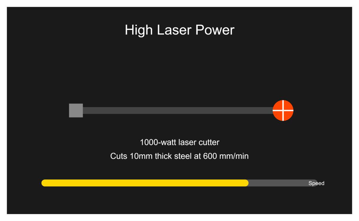
High laser power, measured in watts, allows for faster cutting speeds and the capability to cut through thicker materials. For instance, a 1000-watt laser cutter can efficiently cut through 10mm thick steel at a speed of 600 mm/min. High power settings are particularly suitable for cutting metals, where the increased energy helps achieve deeper penetration and faster processing times.
However, using high laser power can lead to heat damage when cutting thinner materials. Excessive power can cause melting or warping, resulting in wider cut widths and potential quality issues such as rough edges or burn marks. Therefore, while high power can enhance cutting efficiency, it must be carefully managed to avoid compromising the cut quality.
Low laser power is more appropriate for tasks requiring high precision and control. This setting is ideal for cutting thinner or more delicate materials, as it reduces the risk of heat damage and ensures clean, sharp cuts. For example, when cutting 3mm acrylic, a power setting of 50 watts at a speed of 200 mm/min can achieve a clean edge without burning.
The trade-off with low laser power is slower cutting speeds and limited capability with thicker materials. While this setting enhances precision, it may not be efficient for high-volume production or cutting through dense materials. Operators must balance the need for precision with the overall efficiency of the cutting process.
High cutting speeds reduce the time required for each cut, increasing overall productivity. For example, cutting thin sheets of metal at 1000 mm/min can be highly efficient when precision is less critical.
However, faster cutting speeds can lead to quality issues, particularly with thicker materials. High speeds may result in incomplete cuts, rough edges, or increased risk of burn marks due to insufficient interaction time between the laser and the material. For intricate designs or detailed work, slower speeds are often necessary to maintain precision and avoid damaging the material.
Low cutting speeds enhance precision and result in cleaner edges, making them ideal for detailed work or cutting thicker materials. This setting allows for better control over the cutting process, reducing the risk of burning or warping, especially when working with sensitive materials like wood or acrylic.
The downside of slower cutting speeds is increased production time and the potential for heat-affected zones (HAZ). The HAZ refers to the area of the material that experiences a change in properties due to the intense heat from the laser. Prolonged exposure can cause burn marks or discoloration on the material. Operators must find the right balance between speed and precision to achieve the desired cut quality without compromising efficiency.
The relationship between laser power and cutting speed is intricately linked, and striking the right balance is crucial for optimal results. Higher power enables cutting thicker materials or achieving faster cutting speeds, while lower power requires slower speeds for clean cuts in thin materials. For instance, cutting 3mm acrylic might require a speed of 100-150 mm/min with 90-100% power to achieve a clean edge without burning.
Different materials react differently to laser cutting, necessitating specific settings to avoid quality issues. Metals like stainless steel and aluminum can be cut at higher speeds with higher power settings, while materials like wood and acrylic require more precise settings to avoid burning or incomplete cuts.
By carefully managing and adjusting laser power and cutting speed based on the material and desired cut quality, operators can optimize their laser cutting processes, achieving efficient and precise results without damaging the material or the equipment.
The methods to increase laser cutting speed primarily include the following aspects:
Adjusting laser power: The magnitude of laser power directly impacts the cutting speed, seam width, cutting thickness, and cutting quality. Appropriate laser power can enhance cutting efficiency, but it is important to note that the required power depends on the characteristics of the material and the cutting mechanism. For example, when cutting carbon steel, the cutting speed can be increased by changing the type of cutting gas.
Optimizing cutting parameters: Rational settings of cutting speed, power, and gas cutting have a significant impact on cutting quality and efficiency. By simulating cutting plans, the optimal cutting path can be determined to avoid excessive repetition of cuts and travel paths, thereby increasing cutting speed.
Improving the cutting head structure: Choosing the right cutting gas and improving the cutting head structure is also one of the effective methods to increase cutting speed.
Adjusting cutting parameters according to material characteristics: Different metal materials (such as aluminum sheet, stainless steel, carbon steel, copper sheet, and alloy materials, etc.) and material thickness will affect the speed of laser cutting. Therefore, it is necessary to adjust the cutting parameters according to the specific characteristics of the material.
Improving equipment performance: Enhancing the power of the laser generator to reach the ideal value can directly and effectively improve the cutting speed and cutting effect.
Adjusting beam mode and focus distance: By adjusting the mode of the beam and ensuring a change in laser cutting speed within a certain range, pay attention to adjusting laser power, cutting speed, and focus distance to achieve the best cutting effect.
Using an autofocus laser cutting head: The use of an autofocus laser cutting head can improve the machine’s focusing speed, avoiding time wastage caused by manual focusing, thereby indirectly increasing the cutting speed.
Under different laser powers, the key parameters for improving cutting efficiency include cutting speed, laser power, focus size, and focus depth. Firstly, laser power is one of the important factors affecting cutting speed and efficiency. With the increase of laser power, faster cutting speed can be achieved, especially when processing medium and low thickness plates, the increase of laser power can significantly improve cutting efficiency.
In addition, the correct focus position is crucial for obtaining stable and efficient cutting quality. Besides the above parameters, the choice and flow of auxiliary gases also have a significant impact on cutting efficiency.
Oxygen can participate in metal combustion and is suitable for cutting most metals, while inert gases and air are suitable for cutting some metals. This suggests that when choosing the parameters of a laser cutting machine, not only should the laser power and focus settings be considered, but also the choice and flow of auxiliary gases should be adjusted according to the characteristics and requirements of the material being cut.
The key parameters for improving laser cutting efficiency include laser power, cutting speed, focus size, focus depth, and the choice and flow of auxiliary gases. These parameters need to be optimized and adjusted according to the specific cutting task and material characteristics.
In the process of laser cutting, optimizing the beam pattern and focus distance to achieve the best cutting effect is crucial. Initially, the appropriate focus position must be chosen based on different materials and cutting requirements. The position of the focus can influence the fineness of the cut material’s cross-section, the condition of slag at the bottom, and whether the material can be severed.
For instance, in fiber laser cutting machines, the smallest slit and highest efficiency can be achieved when the focus is in the optimal position. Additionally, when the focus of the laser beam is minimized, point shooting is used to establish initial effects, and the focus position is determined based on the size of the light spot effect. This position is the optimal processing focus.
In addition to adjusting the focus position, the beam pattern can be optimized using diffractive multifocal optical elements. These unique diffractive optical components can separate the beam on the focus axis, demonstrating improved bevel cutting effects. Furthermore, a beam shaper is also an important tool that can improve cutting effects by causing incident light to diffract through an optimization algorithm.
In practical operations, it’s crucial to correctly set the focus distance for the cutting effect. Solutions include adjusting to the optimal cutting focus distance, using weights to flatten the material, and using a focus ruler to check whether the height of each area of the worktable is consistent. Moreover, optimizing the distance between processing points is an aspect of improving cutting quality. For example, when the processing point distance is 1 μm, a better quality of the processing cross-section roughness can be obtained.
By precisely adjusting the focus position, optimizing the beam pattern using diffractive optical components and beam shapers, and paying attention to the settings of focus distance and processing point distance, the beam pattern and focus distance during laser cutting can be effectively optimized to achieve the best cutting effect.
The choice of gas in laser cutting processes significantly affects the cutting speed, quality, and overall efficiency. Different gases interact with the material in unique ways, influencing the cut’s precision, edge quality, and the speed at which the laser can move. Understanding these effects is crucial for optimizing laser cutting operations across various materials.
Oxygen is widely used in laser cutting, especially for carbon steel. It facilitates an exothermic reaction with the metal, which enhances the cutting process. This reaction not only helps in dissipating heat but also supports combustion, leading to increased cutting speeds.
Nitrogen is commonly used for cutting stainless steel, aluminum, and other metals where oxidation needs to be prevented. Nitrogen displaces oxygen around the cutting area, preventing the formation of oxides on the cut surface.
Compressed air is often used for cutting non-metallic materials such as wood, plastics, and acrylics. It provides a cooling effect and helps remove debris, but it does not significantly enhance cutting speed for metallic materials.
Argon is an inert gas used for precision cutting, especially for thin materials or when a clean, oxide-free cut is desired. It helps prevent oxidation but does not inherently increase cutting speed.
In summary, selecting the appropriate gas type and optimizing its pressure and purity are essential for achieving the best results in laser cutting. Each gas has its unique advantages and applications, influencing both the cutting speed and the quality of the finished product. By understanding these impacts, operators can make informed decisions to enhance their laser cutting processes.
Optimizing laser cutting speed is crucial for enhancing productivity, improving cut quality, and reducing operational costs. Here are several tips and techniques to achieve optimal laser cutting speeds across various materials and applications:
Adjusting laser power and focal position appropriately is essential for achieving efficient cuts.
Adjust cutting speed based on the material being cut to optimize performance and quality.
Assistive gases play a significant role in laser cutting by improving cut quality and speed.
Monitor and adjust gas flow rates to maintain cut quality and efficiency.
Fine-tune initial piercing and optimize the cutting path for better results.
Maintain a controlled environment and perform regular maintenance to enhance cutting performance.
Adjust repetition rate and frequency based on material characteristics.
Carefully balance cutting speed and quality to achieve optimal results.
By implementing these tips and techniques, operators can optimize laser cutting speeds, achieving efficient, precise, and high-quality cuts across various materials and applications.
Below are answers to some frequently asked questions:
The typical cutting speed for a 1000W laser on carbon steel varies based on the thickness of the material. For thin sheets up to 1 mm, the cutting speed can be relatively high, though specific speeds are not detailed. For medium thicknesses ranging from 1 to 5 mm, the cutting speed is generally around 2-3 meters per minute (m/min). For example, a 1000W laser can cut 5 mm thick carbon steel at approximately 2-3 m/min. When cutting thicker materials up to 10 mm, the speed decreases; for instance, an 8 mm thick carbon steel can be cut at about 1.6 m/min. These speeds are influenced by factors such as laser power, material thickness, and the specific characteristics of the laser cutting machine. Adjusting the cutting speed appropriately is essential to achieve optimal cutting quality and efficiency.
Laser power significantly affects cutting speed in laser cutting processes. Higher laser power allows for faster cutting speeds by delivering more energy to the material per unit time. This increased energy enables the laser to melt and vaporize the material more quickly, thus speeding up the cutting process. Conversely, lower laser power requires slower cutting speeds to ensure complete penetration and maintain cut quality.
Material properties, such as thermal and optical characteristics, also play a crucial role. Materials with high thermal conductivity, like copper and aluminum, need higher laser power or slower cutting speeds to achieve effective cuts. In contrast, materials with lower thermal conductivity, such as stainless steel, can be cut at faster speeds with the same laser power.
The thickness of the material is another important factor. Thicker materials demand more laser power to penetrate fully, necessitating a reduction in cutting speed. For example, cutting 1mm thick mild steel might require a laser power of 1kW and a cutting speed of 20 meters per minute, while cutting 10mm thick mild steel could require 4kW of laser power and a reduced cutting speed of 5 meters per minute.
Assist gas type and pressure also impact the cutting process. Using oxygen as an assist gas can enhance the exothermic reaction, allowing for faster cutting speeds compared to using nitrogen. Additionally, the quality of the laser beam affects the focused spot size and power density, with higher beam quality enabling more precise focusing and higher power density, which supports faster cutting speeds at a given laser power.
While higher cutting speeds can improve production rates, they may compromise edge quality. Slower cutting speeds offer better control and finer quality cuts but reduce production efficiency. Therefore, balancing laser power and cutting speed is essential to achieve optimal results, taking into account material properties, thickness, and desired cut quality.
Optimizing laser cutting speed involves a careful balance of several parameters to ensure both efficiency and quality. Here are the best practices to consider:
Adjust the cutting speed according to the material’s thickness and the desired cut quality. Faster speeds can lead to incomplete cuts or rough edges, while slower speeds can ensure cleaner cuts but may reduce productivity. For thicker materials, slower speeds are generally necessary to ensure complete penetration and minimize defects such as burn marks or dross formation.
Balance power and speed to avoid heat damage and maintain cut quality. Higher laser power allows for faster cutting speeds, especially for thicker materials or more reflective surfaces, but lower power may be more suitable for delicate tasks requiring high precision.
Ensure the focus position of the laser beam is precisely calibrated relative to the material surface to deliver maximum energy and prevent tapered cut edges. For highly conductive materials, positioning the focal point slightly above the material surface can help manage rapid heat dissipation.
Adjust the pulse frequency (repetition rate) appropriately. Higher frequencies can improve the smoothness of cuts in thinner materials by distributing energy more evenly, while lower frequencies are more effective for thicker materials to allow sufficient cooling time between pulses.
Set the assist gas parameters correctly. The type and pressure of the assist gas are crucial. Higher gas flow rates are necessary for thicker materials to effectively remove molten metal, while lower rates are suitable for thinner materials to prevent dispersion of the molten pool. For highly conductive materials like copper and brass, nitrogen assist gas is often used to prevent oxidation and achieve clean cut edges.
Make material-specific adjustments. Different materials respond differently to laser cutting parameters. Metals with high thermal conductivity, such as copper and aluminum, require higher peak power, pulse shaping techniques, and beam wobbling to manage heat dissipation and dross formation. For stainless steel, precise focus and appropriate duty cycle adjustments are essential.
Manage the duty cycle (the percentage of time the laser is active). A higher duty cycle can enhance cutting speed but may lead to overheating and material damage. Adjustments should be based on the material properties to ensure optimal results.
Perform test cuts on scrap material before starting a project to fine-tune power settings, cutting speed, and other parameters. Regularly calibrate the focus position and other settings to maintain high standards of cutting quality.
Consider the cutting pattern, as it can influence how laser power is utilized. Complex patterns may require slower speeds or adjusted power levels to maintain precision without compromising speed. The choice of pattern can also affect heat distribution across the material, impacting the final cut quality.
By carefully adjusting these parameters and considering the specific characteristics of the material being cut, you can optimize the laser cutting speed to achieve efficient and high-quality results.
The choice of gas in laser cutting significantly influences both the cutting speed and the quality of the cut. Different gases are selected based on the type of material being cut and the desired outcome.
Oxygen is commonly used for cutting carbon steel because it reacts exothermically with the material, which enhances the cutting process and allows for faster cutting speeds. However, this reaction can oxidize the edges of the cut, which may be undesirable for certain applications.
Nitrogen is preferred for cutting materials such as stainless steel, aluminum, and copper because it is an inert gas that prevents oxidation, resulting in clean and precise edges. Although nitrogen cutting typically requires high gas pressures, it can achieve faster cutting speeds with higher energy input compared to oxygen.
Argon is used for cutting materials like titanium where nitrogen can react and produce low-quality edges. Argon prevents oxidation and nitridation, but it is more expensive than nitrogen. For ultra-high-quality titanium cutting, an argon/helium blend can be used to achieve faster cut speeds and very clean edges.
Compressed air is the most economical option and is suitable for a broad range of materials, including aluminum and stainless steel. It requires high pressure and low dew point to avoid contamination, but it can introduce minimal oxidation and is less suitable for delicate features on thinner materials.
Regarding cutting speed, oxygen enhances the cutting process by reacting with the material, which generally results in slower cutting speeds due to the exothermic reaction. However, it allows lower power systems to cut thicker materials effectively. Nitrogen can achieve faster cutting speeds due to its inert nature and the high pressure required, which helps in efficiently removing molten material from the cut zone. An argon/helium blend enables faster cut speeds for titanium due to helium’s excellent heat transfer properties.
The choice of gas also impacts cutting quality. Nitrogen and argon produce clean, oxide-free edges, which is crucial for high precision and low tolerance limits. Oxygen can produce oxidized edges, which may be unacceptable in certain applications. The assist gas helps to blow away molten material from the cut, preventing re-deposition and ensuring smooth edges. High gas pressure is critical for this purpose, especially with inert gases like nitrogen and argon. Proper gas pressure ensures that the cutting surface is not rough and the slit is not wide, avoiding partial melting of the cut section.
Gas pressure is another important factor. Insufficient pressure can lead to melting during cutting and reduced production efficiency, while too high pressure can result in a rough cutting surface and a wider slit. The optimal gas pressure varies with the material thickness. For example, when cutting carbon steel, the pressure should decrease with increasing material thickness, while for stainless steel, the pressure should increase with thickness.
In summary, the choice of gas and its pressure is critical for achieving the desired cutting speed and quality. Each gas has its specific advantages and is suited for different materials, and optimizing the gas pressure is essential for maintaining high-quality cuts.

