1. Operation
1.1 Start-up Sequence for Laser Marking Machine
Emergency Stop Switch – Control Switch – Computer – Laser Switch
1.2 Shutdown Sequence for Laser Marking Machine
Laser Switch – Control Switch – Emergency Stop Switch – Computer
1.3 Focal Length Adjustment and Optical Parameter Calibration
Prepare a flat metal plate – Place the plate evenly on the worktable – Launch marking software – Add and select default text – Select processing and continuous processing options, then start marking – Adjust the up-down lever, find the strongest point of the laser on the metal plate – Stop marking and manually align the outer red dot with the inner red dot
2. Process Control Requirements for Laser Marking Posts
2.1 Determine font style according to drawing requirements (including font format, font size, stroke thickness, and text artistry)
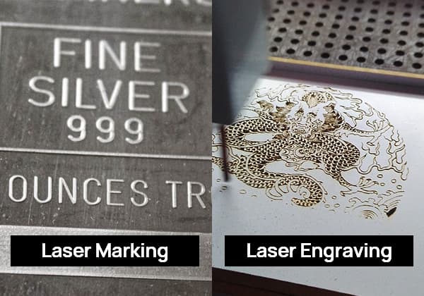
2.2 Interaction of laser with workpiece surface
The high-energy-density laser converges on the workpiece surface, causing changes due to the different surface characteristics of the workpiece. These include surface etching of the workpiece and oxidation of the workpiece surface. Therefore, during marking, the material characteristics should be fully considered to achieve the best effect.
2.3 Laser beam quality
2.3.1 By observing with an up-conversion plate, if the laser beam emitted from under the field lens forms a regular circle and the internal green halo distribution is uniform, it indicates that the beam quality is good. If the light spot forms an ellipse and the internal green halo has defects, it suggests that the beam quality is poor, requiring adjustment using the correct method.
2.3.2 If the light spot is elliptical, you can finely adjust the full reflection and output film frame to make it a regular circle.
2.3.3 If there are obvious defects inside the light spot, then the film surface is contaminated and needs cleaning.
2.3.4 By installing a small aperture diaphragm with a suitable diameter on both ends of the laser rod sleeve, the laser output energy will decrease, but the beam quality will be improved.
2.4 Influence of focal point position
The workpiece surface should be within the focal depth range of about 1mm-2mm. At this time, the laser power density is highest, and the laser etching effect is the best. This is usually identified by adjusting the lifting platform to observe the brightness and sound of the laser on the metal plate to determine whether the workpiece surface is within the focal depth range. Sometimes, to achieve special marking effects, it can be achieved through positive defocusing and negative defocusing.
2.5 Impact of Acousto-Optic Frequency and Pulse Width
Under a constant output current of the laser power supply, peak power can be enhanced (though average power decreases) by reducing the modulation frequency and pulse width of the acousto-optic switch. When the laser peak power is high, it easily forms an etching effect on the workpiece surface. Similarly, by increasing the frequency and pulse width, peak power can be reduced. When the laser’s average power is high, it tends to create a burning effect on the workpiece surface.
2.6 Influence of Galvanometer Scanning Parameters on Marking
The marking parameters set in the marking software greatly impact the marking results. Unreasonable parameter settings can lead to issues such as overly heavy or missed strokes at the start or end of the marking characters, overly heavy turns or arc-shaped turns, and exceeding boundary during high-speed filling of graphics. For instructions on parameter adjustments, please refer to the software manual.
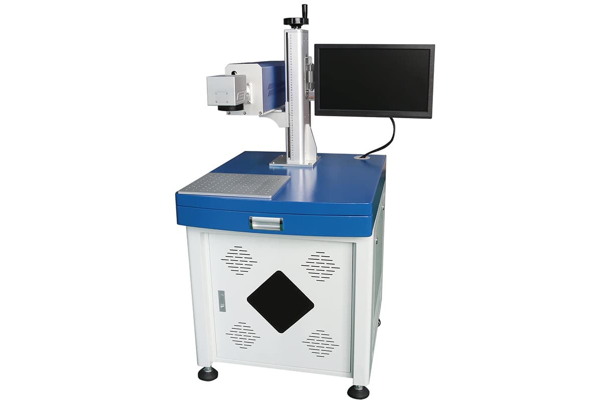
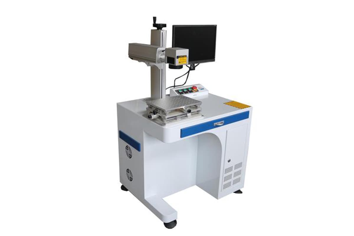
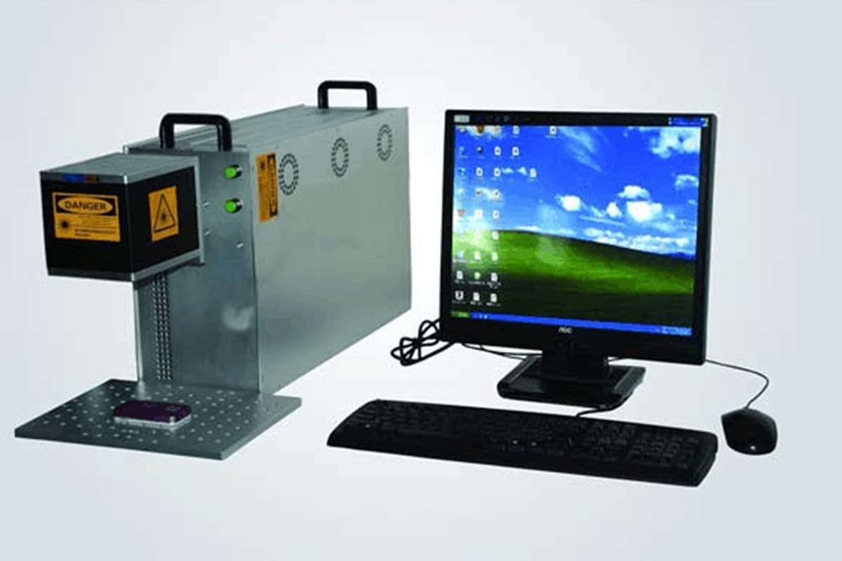
3. Operation of the Laser Marking Machine
3.1 Pre-operation Preparations
3.1.1 For safety assurance, please carefully read this manual.
3.1.2 The laser system employs a water-cooling method and the power supply uses an air-cooling method. If a malfunction occurs in the cooling system, do not operate the machine.
3.1.3 The internal circulating cooling water is deionized water (distilled water). For new equipment, the water should be changed once a month, and after half a year of use, it can be changed every two months.
3.1.4 Ensure the cleanliness of the work environment and that the environmental temperature meets the requirements.
3.1.5 Remember not to directly look at the laser beam during machine operation. Always wear laser protective glasses when working.
3.1.6 During machine operation, the circuit is in a high voltage, high current state. Non-professionals should not perform maintenance or repairs while the machine is on to avoid electric shock. The power supply and laser should be well grounded.
3.1.7 Except for adjusting the laser output power and the overall optical path, troubleshooting should be done with the power supply turned off.
3.1.8 In case of machine failure such as water leakage, electrical arcing, issues with the fuse, or abnormal noises from the laser, immediately cut the power supply.
3.1.9 If the overvoltage or overcurrent protection indicator lights up, immediately turn off the machine.
3.1.10 This machine is not suitable for use in flammable or explosive environments. Avoid using it in places with volatile solvents like alcohol and gasoline.
3.1.11 Do not disassemble this machine at will. For significant failures, notify the manufacturer.
3.2 Machine Operation
3.2.1 Close the main air switch at the back of the machine cabinet.
3.2.2 Insert the key, turn it on, and connect the main system circuit by rotating it 90 degrees clockwise.
3.2.3 Press the water pump switch to operate the cooling system and connect the water pump.
3.2.4 Close the air switch of the laser power supply, press the RUN switch, and the krypton lamp will automatically light up after (5-10) seconds, with the ammeter displaying around 7A.
3.2.5 Adjust the knob to change the output current of the krypton lamp, 17A is appropriate. (The current is set within (7-25)A internally in the power supply, the IGBT will be turned off if it exceeds 33A, and the main relay will be cut off if it exceeds 40A).
3.2.6 Sequentially turn on the computer, scanner, and acoustic-optic indicator buttons.
3.2.7 Enter the WINDOWS operating system, open the laser marking software, set the appropriate parameters, and then proceed with the laser marking work (refer to the software operation manual for software operation).
3.3 Normal Shutdown
3.3.1 Upon completion of the task, sequentially turn off the indicator, scanner, computer, and laser power switch.
3.3.2 Finally, wait for one minute before shutting off the water pump switch. Then pull the air switch to disconnect the power for the entire machine.
4. Safety, Environmental Protection, and Occupational Prevention of Laser Marking Machine Operation
The laser used in the laser marking machine is a Class 4 laser. The output laser is invisible infrared light, which can cause third-degree burns even when off-focus.
The output beam contains both visible and invisible radiation, harmful to the human eye, and direct viewing of the laser beam is prohibited. To prevent accidental exposure of the human eye to the output beam or its reflected beam, all personnel around the equipment must wear specialized safety protective glasses.
Direct viewing of the indicator beam (laser used for indication) is also prohibited, and it should not be directed into other people’s eyes. Although the power of the indicator beam is low, direct viewing is still harmful to the human eye.
5. Issues to Pay Attention to in Daily Machine Operation and Maintenance
5.1 Daily Operation Precautions
a) Avoid direct eye contact with the laser.
b) Use the laser within a controllable area and display warning signs.
c) Unauthorized use is prohibited; only professionally trained personnel may operate the machine.
d) Endeavor to keep the laser head height unequal to eye level.
e) Pay attention to ventilation or exhaust in the laser processing environment.
f) Non-professionals are strictly forbidden to disassemble the machine due to the presence of lasers and high voltage components.
g) Field lenses should be wiped with professional lens paper, using 99% pure alcohol, and only reinstalled after the alcohol has fully evaporated.
h) Protect the laser’s output field lens from smoke produced during operation, preventing the lens surface from getting contaminated. Provide smoke extraction equipment. If the field lens becomes dirty, power may decrease; at this time, gently wipe the surface with degreasing cotton or lens paper soaked in anhydrous alcohol.
i) Strictly prohibit the placement of any unrelated full or diffuse reflective objects within the equipment to prevent laser reflections onto humans or flammable materials.
j) The machine must be supervised while in operation, especially when marking flammable materials, to prevent anomalies or fires. Unauthorized or untrained personnel should not operate the machine. Any damage caused by improper operation is not our company’s responsibility. Operators should always observe the machine’s working condition. As this type of laser is invisible, safety is paramount, and flammable/explosive materials should not be placed within a 2-meter radius of the device.
k) In case of machine malfunction or fire, immediately cut off the power supply.
l) Do not operate the machine when the relative humidity exceeds 80% as this could affect the machine’s lifespan or damage the electronic circuit.
5.2 Maintenance and Care
a) Cleaning of the optical lens
b) Remove the field lens, blow off surface dust, and gently wipe it with alcohol-soaked degreasing cotton. Reinstall it as it was before after cleaning. Handle the lens with care, gently wiping and placing it to prevent dropping. Do not rub it back and forth or use coarse materials for cleaning, as the special metal coating on the lens surface can be damaged, leading to significant laser energy reduction. Check for any leftover fibers or residues after cleaning, and only power on the machine after the alcohol has evaporated.
c) Checking the optical path
d) Please perform a marking test before each startup to ensure the optical path and other components are functioning correctly.
6. Equipment Maintenance and Repair
6.1 Daily Maintenance of the Whole Machine
6.1.1 When the machine is not in operation, the machine cover should be sealed to prevent dust from entering the laser and optical system.
6.1.2 In the event of a malfunction (such as leaks, arcing, blown fuses, unusual noises, etc.), the power supply should be immediately cut off.
6.1.3 The internal circulating cooling water should be replaced regularly as required, with a standard replacement period of once per quarter. If the equipment is used more frequently, the replacement period should be shortened.
6.1.4 For equipment not in use for a long time, the internal cooling water should be drained. In winter, the cooling water temperature should be above zero degrees to avoid the risk of glass tubes within the chamber bursting.
◆ Danger: The machine tool’s circuits are high voltage when operating. Non-professional personnel should not perform maintenance while the machine is on to avoid electrical accidents.
6.2 Maintenance of the Optical System
6.2.1 Due to prolonged use of the device, dust in the air might adhere to the focusing lens, resonator diaphragm, reflective mirror film, and crystal end faces. This could reduce the power of the laser at its minimal or cause the optical lens to overheat and potentially burn or burst at worst.
6.2.2 Cleaning of the optical lens: Mix anhydrous alcohol and ether in a 3:1 ratio. Dip a long-fiber cotton swab or lens paper into the mixture, then gently clean the lens surface in a spiral motion from the center towards the edges. Replace the cotton swab or lens paper after each wipe.
6.2.3 Cleaning of the chamber: After long-term usage of a year, the inner wall of the filter purple glass tube in the chamber might develop a layer of scale due to issues with the water quality of the cooling water, affecting the light output efficiency. It needs to be cleaned (this cleaning should be done under the manufacturer’s guidance).
6.3 Regularly clean the dust on the cooling fan’s net cover and fan blades. The fan’s operation should be observed during the process.
6.4 In summer, when the indoor temperature and humidity are relatively high, condensation may form on the surfaces of the cooled laser crystal and acousto-optic crystals. Use should be stopped at this time, otherwise, the laser film may be damaged.
6.5 Laser processing of workpieces may generate a small amount of spatter and smoke. Long-term usage can cause dirt to adhere to the surface of the field lens protective lens, thus affecting the laser output energy. At this point, the protective lens needs to be cleaned.
7. Fault Analysis and Troubleshooting
7.1 If the “Protection” light is on after the laser power supply is energized, check whether the water pump is on and if the water cooling machine is operating correctly.
7.2 If the “Current” light is on after the laser power supply is energized, you can turn off and restart the laser power supply. If the problem persists, it indicates an internal fault with the laser, which requires specialist repair.
7.3 Misalignment of the optical path may cause the laser energy to weaken. This can be corrected by fine-tuning the diaphragm rack and observing the laser beam output from the field lens using an up-conversion plate, making the green laser spot on the up-conversion plate round and large.
7.4 If light leakage occurs during the marking process, it could be due to improper positioning of the acousto-optic crystal or a power reduction due to a malfunction in the acousto-optic power supply.
7.5 If the laser spot moves only in the horizontal or vertical direction during marking, remove the field lens. With the galvanometer system powered on, gently touch the edge of the galvanometer window. If one lens isn’t locked, it signifies a fault in the single-axis galvanometer system, which requires professional repair.