Imagine a world where welding switchgear cabinets is faster, cleaner, and more efficient. This article dives into the transformative power of laser welding technology, highlighting its key advantages over traditional methods. Learn about the innovations in unit integration, the role of automatic jigs, and the refined laser welding processes that eliminate the need for post-weld grinding. Discover how these advancements are revolutionizing manufacturing, boosting productivity, and enhancing the quality of switchgear cabinets.
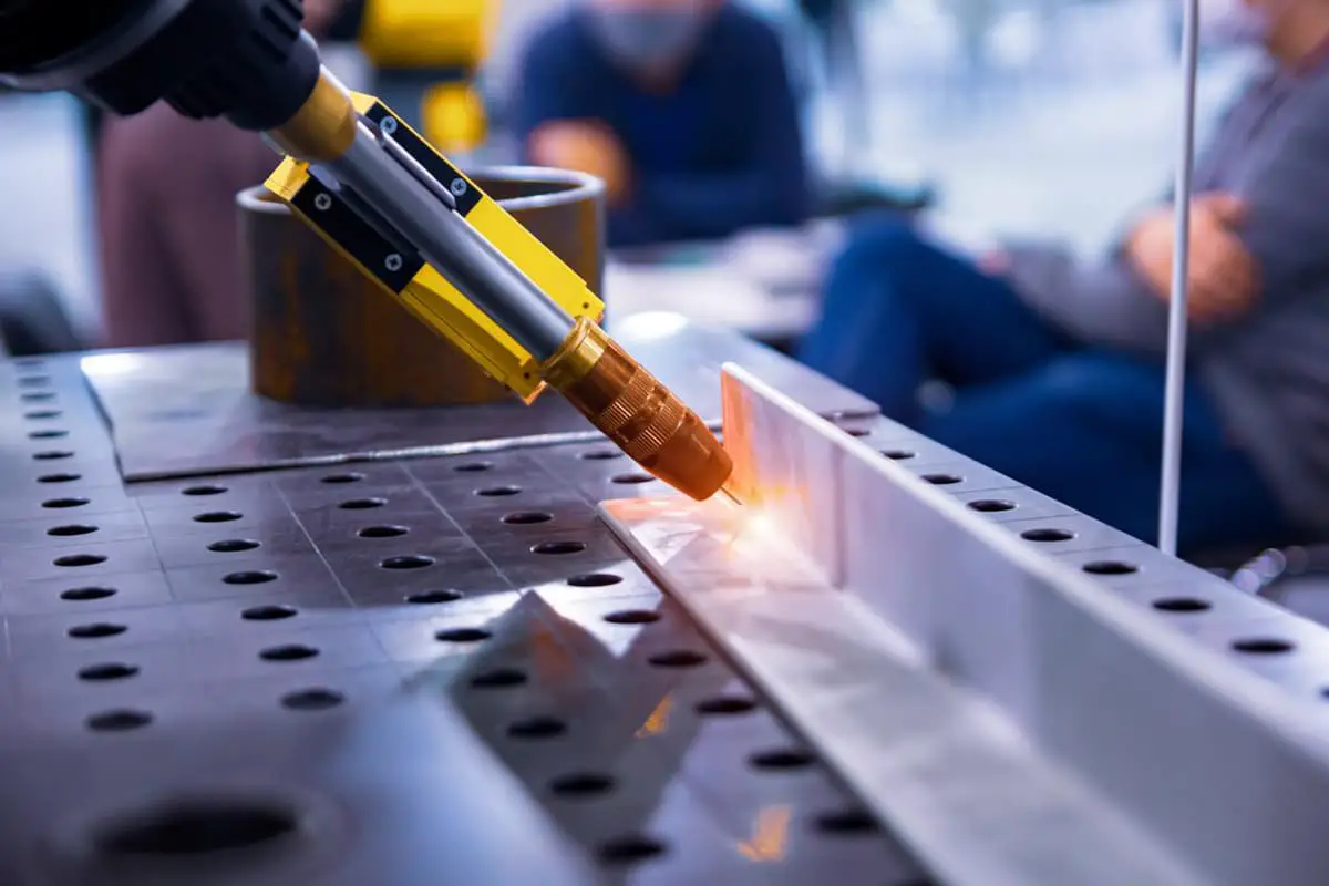
In recent years, with the substantial reduction in the prices of lasers and laser welding heads, the application of laser welding has increased, and it has also been utilized in the welding of switchgear cabinets.
Compared to the traditional arc welding process, arc welding of switchgear cabinets is less efficient and requires substantial post-welding processing.
The advent and promotion of laser welding technology has disrupted this stalemate, not only improving welding efficiency but also eliminating the need for post-welding grinding.
The high-quality weld seams have allowed for a significant breakthrough in the welding process of switchgear cabinets. This article introduces the three key technologies of switchgear cabinet laser welding unit integration, jig, and laser welding process.

Switchgear cabinet welding units typically employ robot welding and dedicated welding machine layouts for unit integration.
Layouts for dedicated welding machines usually correspond to one or a few types of workpieces, with low flexibility and high costs. In contrast, robot welding is more flexible, can accommodate a variety of workpiece sizes and specifications, and is relatively cost-effective.
The most commonly used layout is the dual-station robotic laser welding unit. This unit usually consists of a six-axis robot, dual-station rotating positioner, laser, and protective cabin.
Manual loading is used, and internal welding and external loading and unloading are realized, thereby improving equipment utilization and production efficiency. This is currently the most common unit arrangement for switchgear cabinet welding.
As shown in Figure 1, the rotating positioner is usually equipped with adjustable fixture jigs to meet the welding requirements of different specifications, offering strong versatility. Depending on the client’s different welding process requirements, unit forms in Figures 2 and 4 can also be configured.


At present, switchgear cabinet welding generally adopts arc welding; individual parts are spot-welded together before undergoing continuous welding.
Spot welding is typically carried out manually or with spot welding jigs, while continuous welding usually employs robots or dedicated linear module machines using continuous welding jigs.
Manual spot welding has high skill requirements for workers, as it must ensure both the gap between weld seams and the consistency of spot welding.
The quality of pre-weld spot welding affects the dimensional accuracy and weld seam quality of the subsequent overall cabinet welding.
Spot welding jigs are generally used to ensure the gap and quality of the weld seams, but using them significantly affects welding efficiency and is not suitable for large-scale welding.
Figure 5 shows a switchgear cabinet spot welding jig, where the slide rail is manually adjusted to accommodate multiple specifications for cabinet spot welding.

Figure 6 shows a switchgear cabinet continuous welding jig, which positions the spot-welded workpiece, clamps it using a cylinder and linear module, and realizes continuous welding of various specifications of cabinets through a linear module and rotating module.

Automatic jigs can achieve individual part clamping, positioning, and automatic welding, but they require higher spatial dimensions, structural layouts, transmission, and control.
A typical switchgear cabinet is generally composed of three subcomponents, including the cabinet bent plate and two side sealing plates. The plate thickness is usually only 1.5mm (varying by manufacturer) carbon steel plate, as shown in Figure 7.

Switchgear cabinets come in many specifications and sizes, and all are thin plates. To realize laser welding, the internal support of the cabinet bent plate must first be solved, while also ensuring that the internal support avoids parts after welding. Internal support and external pressing must be able to automatically adjust based on different specifications and sizes.
For large size workpieces, the issues of middle auxiliary support and clamping rigidity must be considered, as well as solving the consistency of long weld seam gaps and the repetitive positioning accuracy of the workpiece welding location.
There should not be overly large seams leading to laser welding strength and quality issues.
Finally, through tight spatial structure design, space must be left for welding, allowing the robot to weld in the most optimal posture.
Figure 8 shows a switchgear cabinet laser welding automatic jig, which can achieve functions such as internal support, part avoidance, and external pressing for different cabinet sizes and specifications.

In addition to ensuring assembly gaps and welding seam positional accuracy through fixtures, the workpiece structure must be appropriately adjusted to meet the laser welding process requirements for the cabinet.
By adding positioning grooves to the bending plate and end plate in the preliminary stage, the quality of cabinet welding in the later stage has significantly improved.
However, the groove size will affect the quality of the subsequent welding seams. Through testing, we have achieved a satisfactory groove size. By conducting batch testing under this groove size, the strength and aesthetics of the welding seams have met customer requirements, as shown in Figure 10.


By employing laser fillet welding, the need for post-welding grinding is eliminated, improving welding efficiency and cabinet aesthetics. However, fillet welding demands strict requirements on the focus distance and the angle of incidence of the welding.
A large amount of welding tests showed that self-fusing fillet requires a large spot to cover the upper and lower plates, hence a large defocus. When obtaining the same spot size, the welding position of the 300mm focus welding head is farther from the protective lens, which is safer.
Simultaneously, under negative defocus, the 300mm focus welding head can be paired with the coaxial blowing component of the 200mm welding head, ensuring that the welding seam is still protected by gas under large defocus.
Extensive testing has shown that changing the angle of incidence to 35° yields the best welding results. Figure 11 compares the welding effects at different angles of incidence.

(1) The switch cabinet body laser welding uses a dual-station robot laser welding unit to achieve internal welding and external loading and unloading, improving equipment utilization and production efficiency.
(2) The switch cabinet body laser welding is equipped with a dedicated automatic fixture, enabling all functions such as internal support for different specification sizes, part avoidance, and external clamping.
(3) The switch cabinet body laser welding adopts a positioning groove structure and fillet welding process, eliminating the need for post-weld grinding, improving welding efficiency and cabinet aesthetics, and addressing the issue of poor welding quality of the switch cabinet body.

As the founder of MachineMFG, I have dedicated over a decade of my career to the metalworking industry. My extensive experience has allowed me to become an expert in the fields of sheet metal fabrication, machining, mechanical engineering, and machine tools for metals. I am constantly thinking, reading, and writing about these subjects, constantly striving to stay at the forefront of my field. Let my knowledge and expertise be an asset to your business.

